Phase identification system and method

a phase identification and phase technology, applied in the field of phase identification, can solve the problems of significant phase differences, affecting calibration, and affecting the phase identification of transmission lines

Inactive Publication Date: 2011-06-02
GENERAL ELECTRIC CO
View PDF5 Cites 26 Cited by
  • Summary
  • Abstract
  • Description
  • Claims
  • Application Information

AI Technical Summary

Problems solved by technology

Utility companies experience difficulties in identifying the phase of a transmission line in the distribution network.
The inability to identify the phase information of a given conductor causes operational problems such as difficulty in shifting the customer loads from one phase to another under emergency conditions, or when planning future load expansion.
A series of data conversions and transmissions required in such embodiments causes inductive and / or capacitive delays, often resulting in significant phase differences.
However, this approach relies heavily on telephone companies that operate by route switching and signals on telephone lines that are sometimes rerouted over circuits, which may vary by hundreds of miles.
The additional phase shift introduced by the time delay associated with such rerouting may affect the calibration.

Method used


Image

  • Phase identification system and method
  • Phase identification system and method
  • Phase identification system and method

Examples


Embodiment Construction

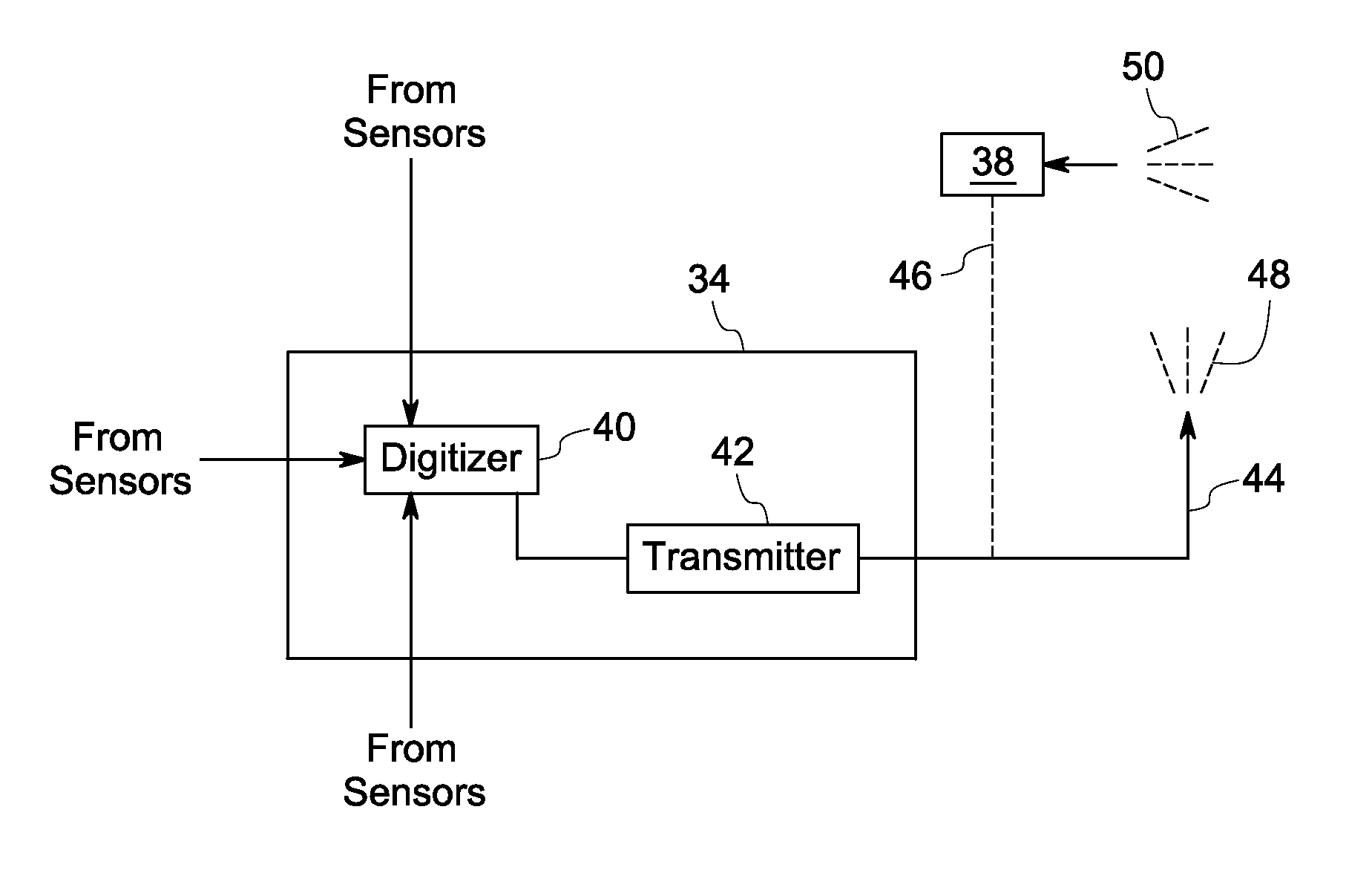
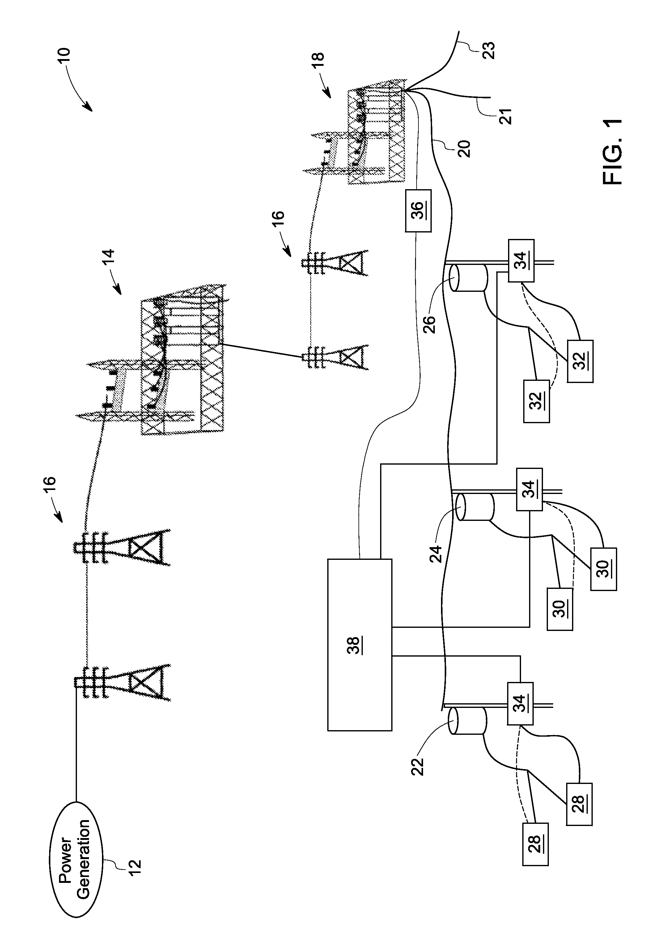
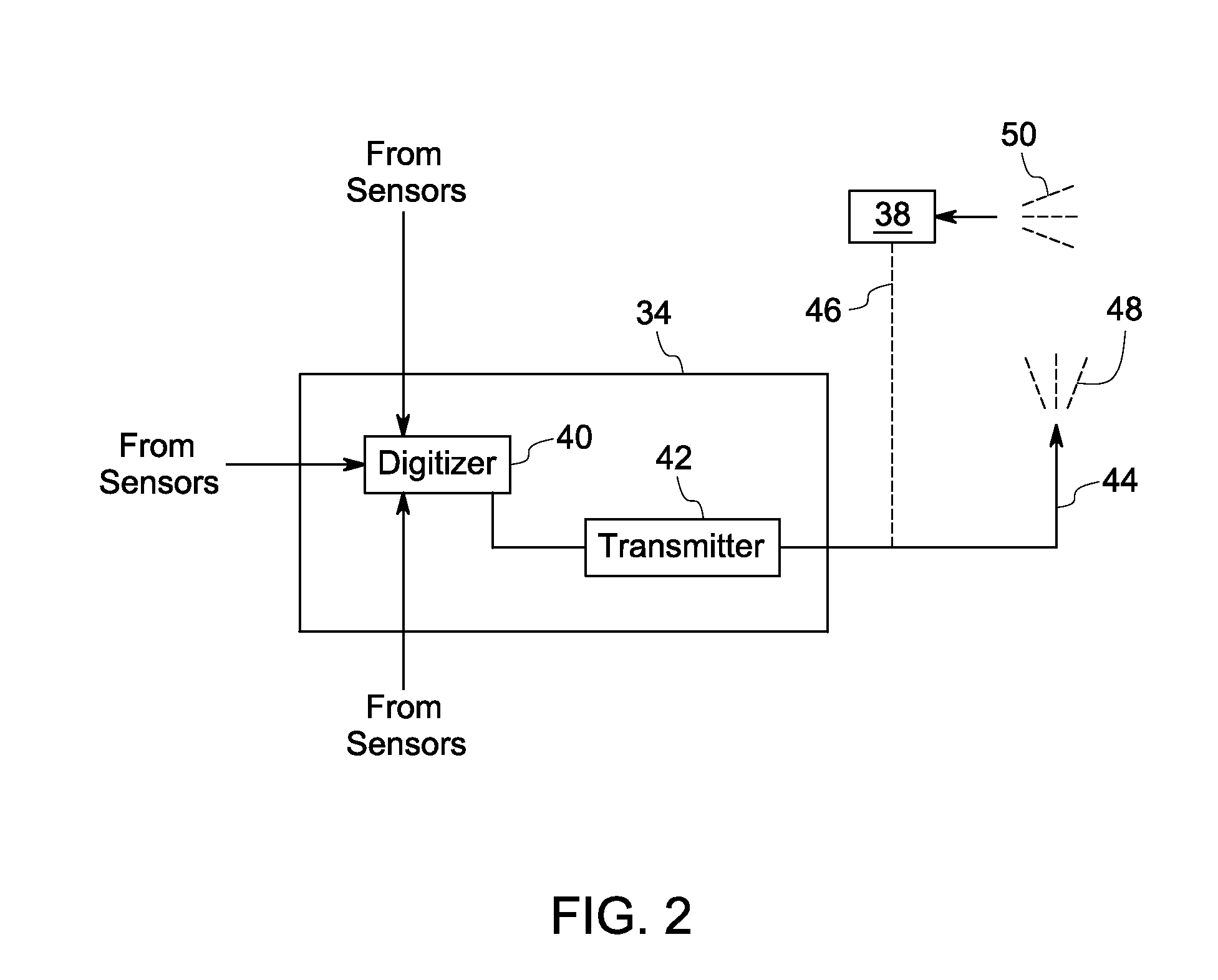
[0017]FIG. 1 illustrates an electrical distribution network implementing a phase identification system according to an embodiment of the invention. The distribution network 10 includes transmission lines to transfer power generated at a power generation site 12 to one or more end users. Power generation site 12 may include, for example, one or more hydro, thermal, nuclear, or combined gas cycle power plants. Power from the generation site 12 is transmitted at high voltages via high voltage transmission lines 16. High voltage is stepped down to intermediate voltage at transmission substation 14. Further downstream, the intermediate voltages are further stepped down to medium voltage at distribution substation 18. Feeder lines 20 couple the distribution substation to distribution transformers 22,24,26 that supply power to end users such as industrial or residential consumers 28,30,32. For the sake of simplified illustration, a single power generation site, single distribution substati...


PUM


Abstract

A method to identify phase is presented. The method includes obtaining electrical parameters at a node and a substation of an electrical grid, processing the electrical parameters of the node and the substation into processed electrical parameters comprising at least one of a voltage harmonic amplitude, a current harmonic amplitude, a geometric harmonic modulated signal, and a noise pattern. The method further includes comparing the processed electrical parameters from the node and the substation and identifying phase information of the node with respect to the substation.

Description

BACKGROUND[0001]The subject matter disclosed herein generally relates to phase identification and in particular to characterization of a power distribution network via phase identification.[0002]Typically, power distribution networks carry voltages in three phases that consist of 50 Hz or 60 Hz sine waves that are each out of phase by approximately 120°. The three-phase power is generated in a power plant or other power source and distributed across a wide area to provide power to multiple loads such as residences and businesses. A three-phase power transmission line generally has three transmission conductors, one for each phase, and sometimes a neutral conductor as a fourth conductor.[0003]Utility companies experience difficulties in identifying the phase of a transmission line in the distribution network. The inability to identify the phase information of a given conductor causes operational problems such as difficulty in shifting the customer loads from one phase to another unde...

Claims


Application Information

Patent Timeline
Patent Type & Authority Applications(United States)
IPC IPC(8): G06F19/00
CPCG01R19/2513G01R19/2506
Inventor KOSTE, GLEN PETERHERSHEY, JOHN ERIKTOMLINSON, JR., HAROLD WOODRUFFBONANNI, PIERINO GIANNIKOLWALKAR, AMOL RAJARAM
Owner GENERAL ELECTRIC CO
Why Eureka
Try Eureka