Capacitive touch panel and display device with touch detection function

Inactive Publication Date: 2011-06-09
JAPAN DISPLAY WEST
View PDF5 Cites 89 Cited by
  • Summary
  • Abstract
  • Description
  • Claims
  • Application Information

AI Technical Summary

Benefits of technology

[0014]According to the capacitive touch panel and the display device with the touch detection function according to the embodiment of the present invention, when a contact position or an adjacent position by the object is detected based on the detection signal determined by the touch detection electrode according to a change of the electrostatic capacitance, the first series of sampling signal including the signal component with first level and the noise component, and the second series of sampling signal including the signal component with

Problems solved by technology

However, in the drive method and the detection method of the capacitive touch panel disclosed in Patent Document 1 described above, since it is necessary to sequentially switch frequencies of the drive signals to select the conditions not influenced by the disturbance-noise, there is a possibility that it takes time for

Method used


Image

  • Capacitive touch panel and display device with touch detection function
  • Capacitive touch panel and display device with touch detection function
  • Capacitive touch panel and display device with touch detection function

Examples


first embodiment

2. First Embodiment

Structural Example

Overall Structural Example

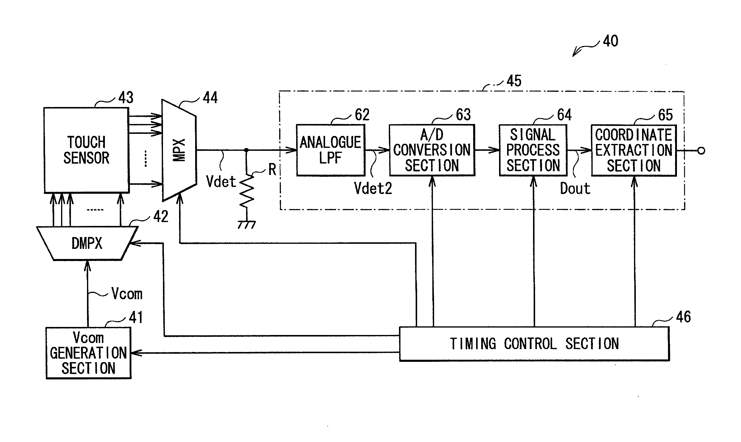
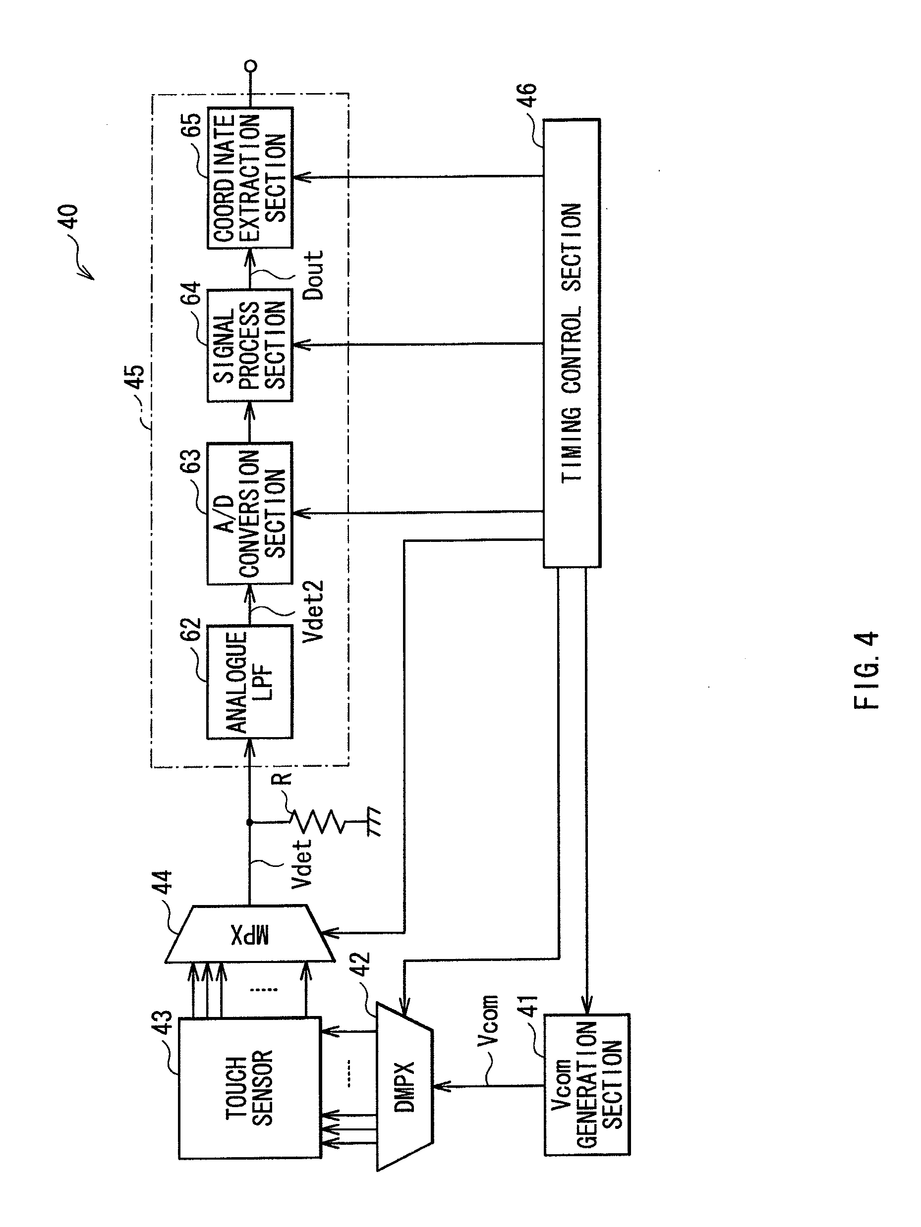
[0048]FIG. 4 illustrates a structural example of a capacitive touch panel 40 according to a first embodiment of the present invention. The capacitive touch panel 40 includes a Vcom generation section 41, a demultiplexer 42, a touch sensor 43, a multiplexer 44, a detecting section 45, a timing control section 46, and a resistance R.

[0049]The Vcom generation section 41 is a circuit generating the drive signal Vcom driving the touch sensor 43. Here, in the drive signal Vcom, its duty ratio is slightly shifted from 50%, as will be described later.

[0050]When the drive signal Vcom supplied from the Vcom generation section 41 is supplied to a plurality of drive electrodes of the touch sensor 43 one after another, which will be described later, the demultiplexer 42 is a circuit switching its supply destination.

[0051]The touch sensor 43 is a sensor detecting a touch based on the basic principle of the electrostatic capacitance ty...

modification 1-1

[0131]In the above-described embodiment, although the touch component is extracted in the timing in the vicinity of the fall of the drive signal Vcom, instead of this, the touch component may be extracted in the timing in the vicinity of the rise of the drive signal Vcom.

modification 1-2

[0132]In the above-described embodiment, although the polarity-alternating waveform in which the duty ratio is slightly shifted from 50% is used as the waveform of the drive signal Vcom, it is not limited to this, and instead of this, the waveform including two polarity-alternating waveforms Y1 and Y2 in which the phases are shifted from each other may be used, for example, as illustrated in FIG. 24. In this case, for example, the sampling timing may be like FIG. 24(C), or like FIG. 24(D). In FIG. 24(C), all the three sampling timings A1 to A3 are positioned immediately before the rise of the polarity-alternating waveform Y1. Meanwhile, in the three sampling timings B1 to B3, B1 and B2 exist immediately before the rise of the polarity-alternating waveform Y1, and B3 is positioned immediately after the rise. Further, in FIG. 24(D), all the three sampling timings A1 to A3 are positioned immediately before the fall of the polarity-alternating waveform Y1. Meanwhile, in the three sampli...


PUM


Abstract

A capacitive touch panel capable of reducing a disturbance noise and reducing touch detection time with a simple structure is obtained. The capacitive touch panel includes: a plurality of drive electrodes each to which a drive signal for touch detection is applied; a plurality of touch detection electrodes arranged to intersect the plurality of drive electrodes, and each outputting a detection signal synchronized with the drive signal; a first sampling circuit (A/D conversion circuits 72 and 73) extracting a first series of sampling signal including a signal component with first level and a noise component, from the detection signal; a second sampling circuit (A/D conversion circuits 75 and 76) extracting a second series of sampling signal including a signal component with second level different from the first level and the noise component, from the detection signal; a filter circuit (digital LPFs 81 and 82) performing a high range cut process on the first series of sampling signal and the second series of sampling signal; and a computation circuit (a subtraction circuit 90) determining a signal for touch detection based on an output of the filter circuit.

Description

TECHNICAL FIELD[0001]The present invention relates to a touch panel capable of information input by contact or proximity of a user's finger or the like, in particular, to a capacitive touch panel detecting a touch based on a change of an electrostatic capacitance, and a display device with an electrostatic capacitance type touch detection function.BACKGROUND ART[0002]In recent years, a display device capable of information input by mounting a contact detection device, which is a so-called touch panel, on a display device such as a liquid crystal display device, and displaying various button images on the display device instead of typical mechanical buttons has attracted attention. There are several methods of the touch panel, such as an optical method and a resistance method, and a capacitive touch panel capable of realizing low consumption power while having a relatively-simple structure has been expected, in particular, in a portable terminal or the like. However, in the capacitiv...

Claims


Application Information

Patent Timeline
IPC IPC(8): G06F3/044
CPCG06F3/0412G06F3/044G06F3/0418G06F3/04182G06F3/0445G06F3/0446
Inventor KIDA, YOSHITOSHIISHIZAKI, KOJINOGUCHI, KOUJITAKEUCHI, TAKEYAHARADA, TSUTOMUNAKANISHI, TAKAYUKI
Owner JAPAN DISPLAY WEST
Why Eureka
Try Eureka