Inspection Method and Apparatus, and Corresponding Lithographic Apparatus

a lithographic apparatus and inspection method technology, applied in the direction of measuring devices, material analysis through optical means, instruments, etc., can solve the problems of significant measurement error, poor electrical contact between structures, and devices that cannot meet specifications, and achieve the effect of limiting the effect of linearity error

Active Publication Date: 2011-06-09
ASML NETHERLANDS BV
View PDF34 Cites 21 Cited by
  • Summary
  • Abstract
  • Description
  • Claims
  • Application Information

AI Technical Summary

Benefits of technology

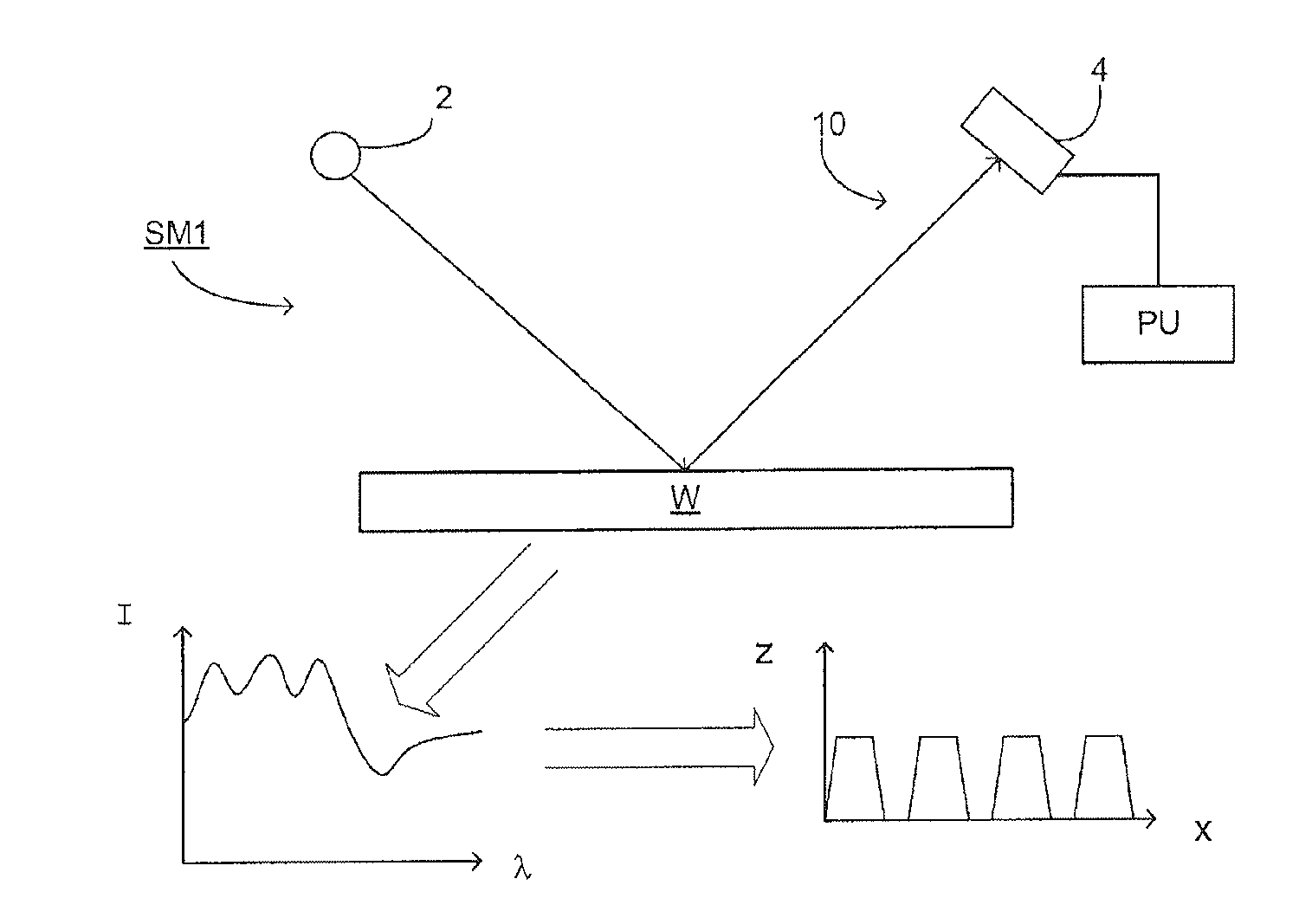
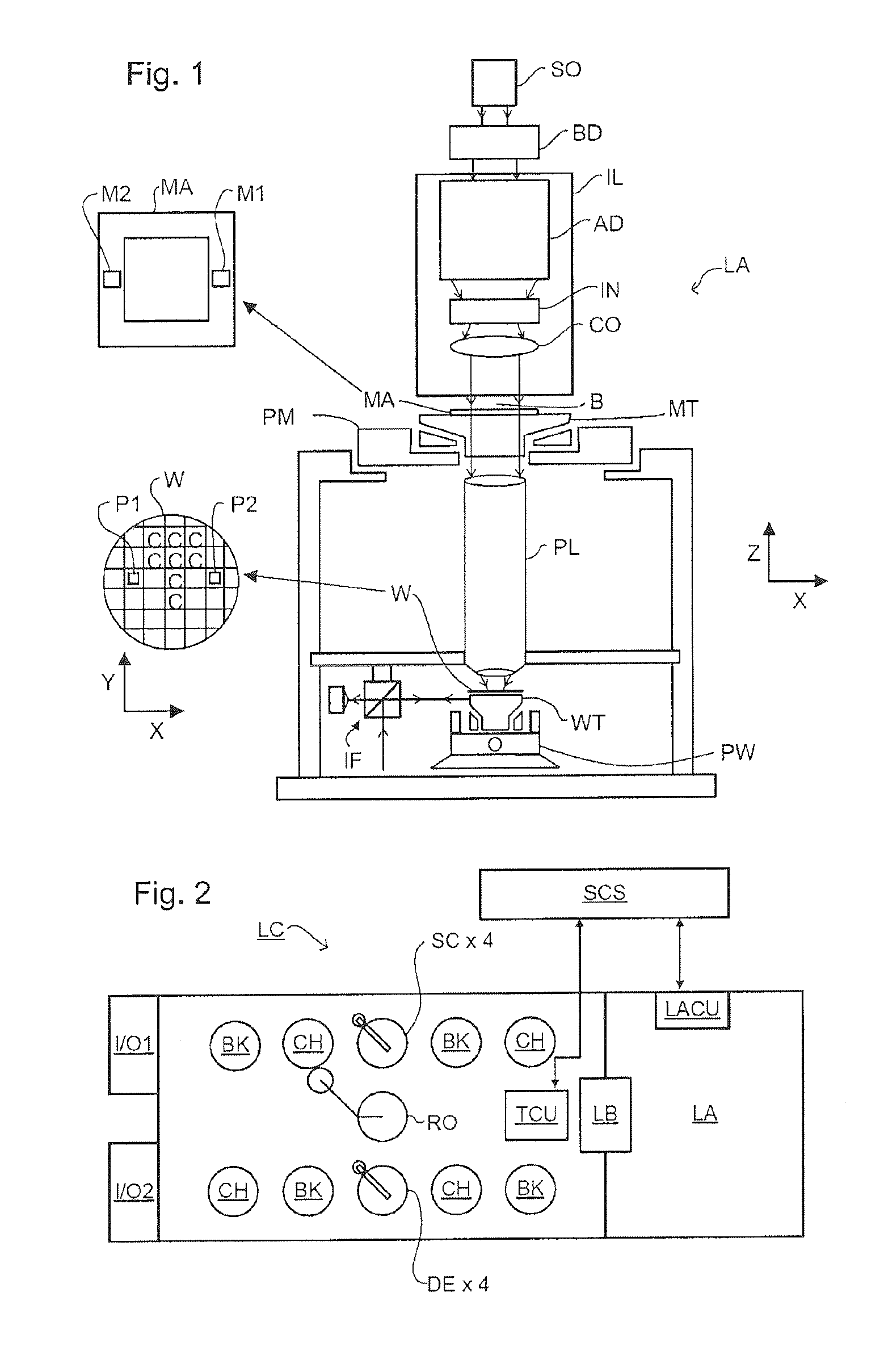
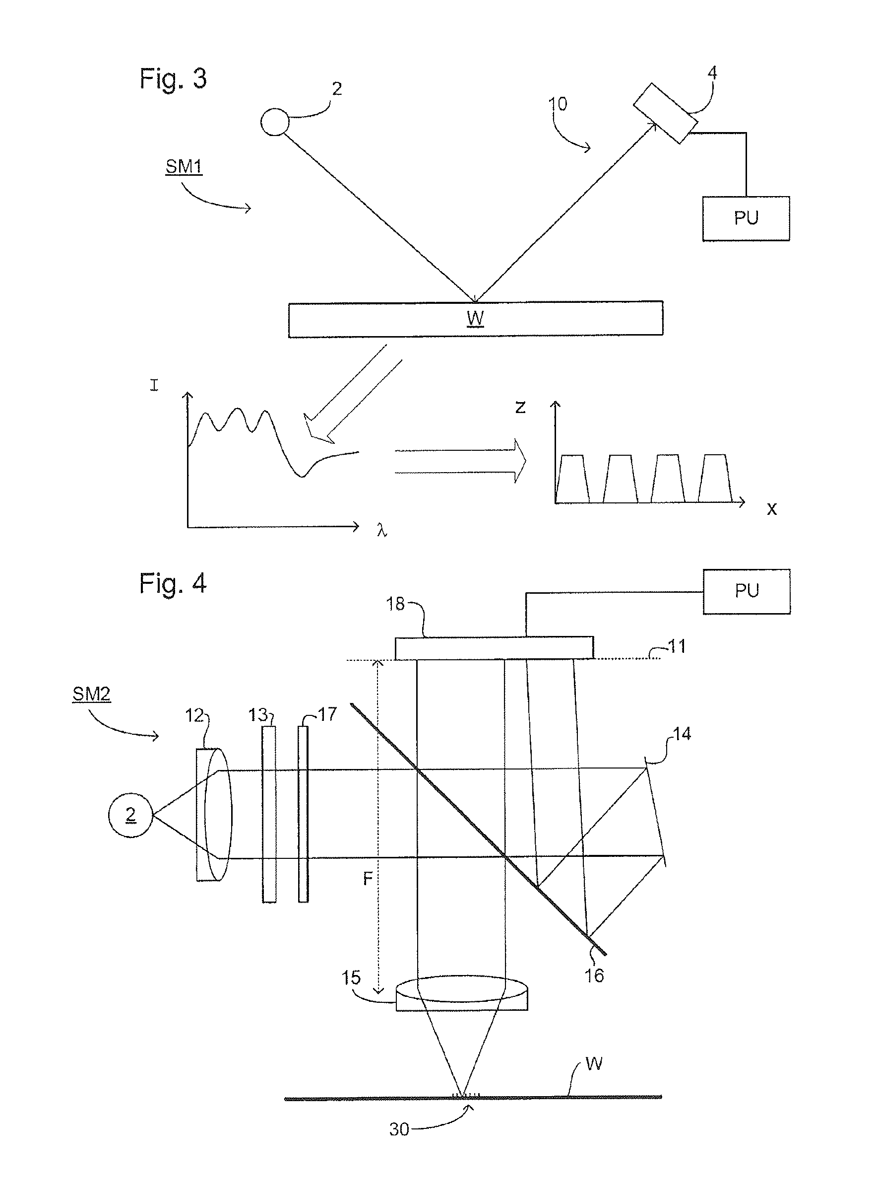
[0011]According to an aspect of the present invention, there is provided a method to determine an overlay error on a substrate comprising: projecting a beam of radiation onto three or more targets, each comprising first and second overlapping patterns with predetermined overlay offsets, on the substrate, measuring the asymmetry of the radiation reflected from each target on the substrate, and determining the overlay error not resultant from the predetermined overlay offsets, determining a function to enable calculation of overlay from asymmetry for other points on the wafer, where the determining the function includes limiting the effect of linearity error when determining the overlay error from the function.
[0012]According to a second aspect of the present invention, there is provided

Problems solved by technology

Successive layers or multiple processes on the same layer must be accurately aligned to the previous layer, otherwise electrical contact between structures will be poor and t

Method used


Image

  • Inspection Method and Apparatus, and Corresponding Lithographic Apparatus
  • Inspection Method and Apparatus, and Corresponding Lithographic Apparatus
  • Inspection Method and Apparatus, and Corresponding Lithographic Apparatus

Examples


Embodiment Construction

[0024]This specification discloses one or more embodiments that incorporate the features of this invention. The disclosed embodiment(s) merely exemplify the invention. The scope of the invention is not limited to the disclosed embodiment(s). The invention is defined by the claims appended hereto.

[0025]The embodiment(s) described, and references in the specification to “one embodiment”, “an embodiment”, “an example embodiment”, etc., indicate that the embodiment(s) described may include a particular feature, structure, or characteristic, but every embodiment may not necessarily include the particular feature, structure, or characteristic. Moreover, such phrases are not necessarily referring to the same embodiment. Further, when a particular feature, structure, or characteristic is described in connection with an embodiment, it is understood that it is within the knowledge of one skilled in the art to effect such feature, structure, or characteristic in connection with other embodimen...


PUM


Abstract

A method and associated apparatus determine an overlay error on a substrate. A beam is projected onto three or more targets. Each target includes first and second overlapping patterns with predetermined overlay offsets on the substrate. The asymmetry of the radiation reflected from each target on the substrate is measured. The overlay error not resultant from the predetermined overlay offsets is determined. The function that enables calculation of overlay from asymmetry for other points on the wafer is determined by limiting the effect of linearity error when determining the overlay error from the function.

Description

CROSS REFERENCE TO RELATED APPLICATIONS[0001]This application claims benefit under 35 U.S.C. 119(e) to U.S. Provisional Patent Application No. 61 / 267,633, filed Dec. 8, 2009, which is incorporated by reference herein in its entirety.BACKGROUND[0002]1. Field of the Invention[0003]The present invention relates to methods of inspection usable, for example, in the manufacture of devices by lithographic techniques[0004]2. Background Art[0005]A lithographic apparatus is a machine that applies a desired pattern onto a substrate, usually onto a target portion of the substrate. A lithographic apparatus can be used, for example, in the manufacture of integrated circuits (ICs). In that instance, a patterning device, which is alternatively referred to as a mask or a reticle, may be used to generate a circuit pattern to be formed on an individual layer of the IC. This pattern can be transferred onto a target portion (e.g., comprising part of, one, or several dies) on a substrate (e.g., a silicon...

Claims


Application Information

Patent Timeline
IPC IPC(8): G01N21/956
CPCG03F7/70633G01N21/956
Inventor FUCHS, ANDREASVAN DER SCHAAR, MAURITSMIDDLEBROOKS, SCOTT ANDERSONBINTEVINOS, PANAGIOTIS PIETER
Owner ASML NETHERLANDS BV
Why Eureka
Try Eureka