Reinforced illuminable safety rope and deployment system

a safety rope and illuminating technology, applied in the field of safety ropes, can solve the problems of firefighters being constantly forced to enter darkened, smoke-filled environments, and reducing their ability to see, and achieve the effect of increasing strength

Inactive Publication Date: 2011-06-09
FELDMAN HAROLD +1
View PDF12 Cites 8 Cited by
  • Summary
  • Abstract
  • Description
  • Claims
  • Application Information

AI Technical Summary

Benefits of technology

[0013]The disadvantages associated with the prior art are overcome by the present invention which provides an illuminable safety rope and deployment system. In one embodiment, an illuminable safety rope includes an illuminable wire having a predetermined length and an insulative covering surrounding the illuminable wire along the length to thereby form an illuminable cable. In one embodiment, the illuminable wire includes an electroluminescent (EL) wire. In another embodiment, the illuminable wire includes fiber optic filaments. Alternatively, the illuminable wire includes light emitting diodes (LEDs). The insulative covering includes a flange extending radially outward along the length of the illuminable cable, where the flange is defined by opposing side portions that terminate at an edge portion. A fabric material is disposed over and secured to the opposing side and edge portions at least the length of the illuminable cable to thereby form the safety rope. A portion of the illuminable cable opposite the flange transmits light to illuminate the safety rope along its length when the illuminable wire receives power. The illuminating safety rope is especially useful in during dark or hazardous operations where visual conditions are severely hampered by, for example, in smoke-filled and / or gas-filled environments, during night time operations or when submerged under water. Moreover, its increased strength enables rescuers to support or pull weights greater than 1000 lbs.
[0017]In one embodiment, directional or distance markers can be provided on the flat surface of the safety rope. The directional or distance markers can assist a responder in identifying his position relative to the starting point and / or in returning safely to the point of entry of a rescue site.
[0018]In another embodiment, loop knots, such as lineman loop knots, can be provided to enable additional safety ropes to be attached to a primary safety rope. In this manner two or more responders can enter a rescue site and branch out in different directions to perform a search. The loop knots loop around the primary safety rope and the secondary safety ropes can be attached to the loop knots using a fastener, such as a carabiner. The loop knots can include reflective tape or other reflective materials that assist rescuers in seeing the loop knot from the reflected light of the illuminated safety rope, thereby making it easy to latch on, for example, using a carabiner.

Problems solved by technology

For example, firefighters are constantly forced to enter darkened, smoke-filled environments.
Their ability to see is greatly diminished, and the risk of losing their way out, even with a conventional safety rope to help guide them is extreme.
Under best conditions it is often difficult for a person being rescued to find and grab a hold of the rescue rope.
Adverse conditions, such as low visibility during nightfall, adverse weather conditions, choppy sea conditions, among other hazardous conditions frustrate rescue operation even further.
To overcome some of the adverse conditions, marine safety operatives often use high powered flood lights to illuminate the person being rescued, however the use of such lighting can temporarily blind and cause difficulty for such person to locate the throw rope.
The lack of visibility of these throw ropes has hampered emergency operations, protracting the time and ease of rescue.
The reel and drum are cumbersome, inflexible, and add undesirable weight to the rescuer's equipment load.
Further, the reel cannot be carried by the rescuer in a convenient manner, as it is either carried by hand or bucked to a belt.
Moreover, the EL cable can snag or otherwise bind and / or become entangled on the reel when being unspooled during deployment.
Although the bag is lighter in weight than the aforementioned reel and drum deployment system, the EL wire is prone to snag, knot or otherwise become entangled while being deployed from the bag if the EL wire is not properly spooled or wound therein:

Method used


Image

  • Reinforced illuminable safety rope and deployment system
  • Reinforced illuminable safety rope and deployment system
  • Reinforced illuminable safety rope and deployment system

Examples


first embodiment

[0052]Referring to FIG. 4, a first embodiment illustrating a section of the illuminable safety rope 100 of FIG. 1 is shown. The safety rope 100 includes an electroluminescent (EL) wire 402 having a predetermined length and an insulative covering 408 surrounding the EL wire 402 along the length, which together forms the EL cable 102. The EL wire 402 is formed by a core conductor or electrode 404 and a second electrode having luminescent particles or coating formed thereon. The fabrication and operation of the EL wire is provided for better understanding, but does not form a part of the present invention. However, for a detailed understanding of the fabrication and operation of an illustrative EL wire 402, as well and an EL cable 102, the disclosures of previously noted U.S. Pat. Nos. 3,819,973 and 5,869,930 provide illustrative examples.

[0053]The insulative covering 408 has a flange 410 protruding (i.e., extending) radially outward along the length “M” of the EL cable 102. The flange...

second embodiment

[0056]Referring to FIG. 5, the safety rope 500 is illustratively shown. The safety rope 500 includes the same EL cable 102 with the flange 410 as shown in FIG. 4, however, a flexible reinforcing wire 502 is positioned adjacent the edge portion 418 of the flange 410. The reinforcing wire preferably extends along the length “M” of the EL cable 102. Illustrative examples of a flexible reinforcing wire 502 suitable for use include copper or aluminum wires having a gauge in the range between 18 and 10 (AWG) or a cross-sectional area of 0.8 mm to 5.5 mm, although such dimensions are not considered limiting. A reinforcing wire fabricated from a non-metal material, such ceramic, glass rope and the like are also suitable for use in the present invention.

[0057]During manufacture, the pre-cut length of fabric is placed along the lower portion 414 of the flange 410 and wrapped around the reinforcing wire 502 positioned adjacent the flange edge 418, and over the top portion 416 of the flange 410...

third embodiment

[0059]Referring to FIG. 7, the safety rope 700 is illustratively shown. The safety rope 600 is the same as the safety rope 500 of FIG. 6, except that the reinforcing wire 702 includes two core elements 704 with an insulation cover, such as zip cord or twisted pair, positioned on the top portion 416 or bottom portion 414 (i.e., a side portion) of the flange 410. The fabric material 104 is wrapped around the bottom portion 414 and edge 418 portions of the flange 410, and then over double core reinforcing wire 702. The fabric 104 is then stitched 420 along the top and bottom of the safety rope 100 and through the opposing sides of the flange 410 as described above.

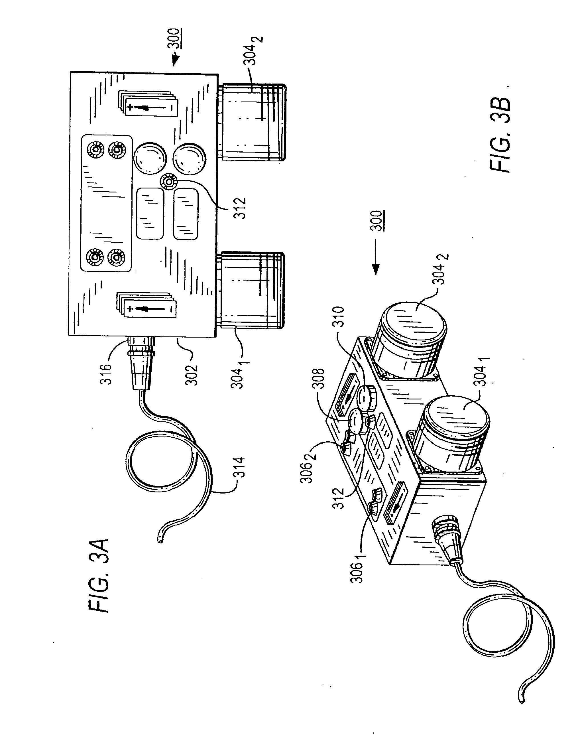
[0060]The safety rope 700 of FIG. 7 can be especially useful for providing a communication signal path to send a distress signal to other responders. In particular, the paired wire elements 704 can be coupled to a switch or button on the power supply 300 which can be activated to send an electrical signal from the responder t...


PUM

PropertyMeasurementUnit
weightsaaaaaaaaaa
angleaaaaaaaaaa
weightsaaaaaaaaaa

Abstract

An illuminable safety rope includes an illuminable wire of a predetermined length surrounded by a light-transmitting insulative covering to thereby form an illuminable cable. The insulative covering includes a flange extending radially outward along its length. The flange is defined by opposing side portions and terminates at an edge portion. A fabric material is disposed over and secured to the opposing side and edge portions along at least the length of the illuminable cable to thereby form the safety rope. At least a portion of the illuminable cable opposite the flange transmits light to illuminate the safety rope along its length when the illuminable wire receives power. Additional floatation materials and / or wiring can be provided adjacent the flange and beneath the fabric to enable floatation and / or reinforcement of the rope, or a distress signal to be sent to an alarm.

Description

CROSS REFERENCE TO RELATED APPLICATION[0001]This patent application claims benefit under 35 U.S.C. §371 to international application No. PCT / US2009 / 004331, filed on Jul. 22, 2009, which claims priority to U.S. Provisional Application, Ser. No. 61 / 087,449, filed Aug. 8, 2008, the contents of which are incorporated by reference herein in its entirety.BACKGROUND OF THE INVENTION[0002]1. Field of Invention[0003]The present invention relates to safety ropes, and more specifically to an illuminable safety rope and a method and system for fabricating and deploying the same.[0004]2. Description of the Related Art[0005]Safety ropes having various characteristics have been developed to reduce risk to users when endeavoring to overcome hazardous environments. For example, emergency responders such as fire fighters and other rescue personnel exposed to hazardous conditions or environments have often found it useful to include one or more safety ropes to guide or climb as they enter and exit a d...

Claims


Application Information

Patent Timeline
Patent Type & Authority Applications(United States)
IPC IPC(8): F21V33/00H01R43/00
CPCD07B1/20F21S4/003B63B2201/08D07B5/005F21Y2105/006A62B3/00D07B1/148Y10T29/49117G02B6/001D07B2501/2092B63C9/26F21S4/20F21Y2105/00F21Y2115/20
Inventor FELDMAN, HAROLDDANIELI, GUY
Owner FELDMAN HAROLD
Why Eureka
Try Eureka