Light uniformization structure and light emitting module

Active Publication Date: 2011-06-09
IND TECH RES INST
View PDF19 Cites 19 Cited by
  • Summary
  • Abstract
  • Description
  • Claims
  • Application Information

AI Technical Summary

Benefits of technology

[0015]The light uniformization structure and the light emitting module of the disclosure use a low refractive index layer and surface structures in combination to achieve a uniform light field and high transmittance. Moreover, the total reflection inside the light

Problems solved by technology

However, the light emitting principle and light emitting mode of the LED are quite different from the conventional light sources such as bulbs a

Method used


Image

  • Light uniformization structure and light emitting module
  • Light uniformization structure and light emitting module
  • Light uniformization structure and light emitting module

Examples


Embodiment Construction

[0057]The disclosure provides a light uniformization structure and a light emitting module that use a low refractive index layer and surface structures in combination to achieve a uniform light field and high transmittance. Moreover, the total reflection inside the light uniformization structure is reduced by using a geometrical-optics refraction mechanism (high refractive index layers clamping low refractive index layer), thereby improving the luminous efficiency of the light uniformization structure and the light emitting module.

[0058]In the following descriptions, “first” and “second” are merely used for denoting two elements (two surfaces, two material layers, or two basic materials), instead of specifying particular elements or sequences.

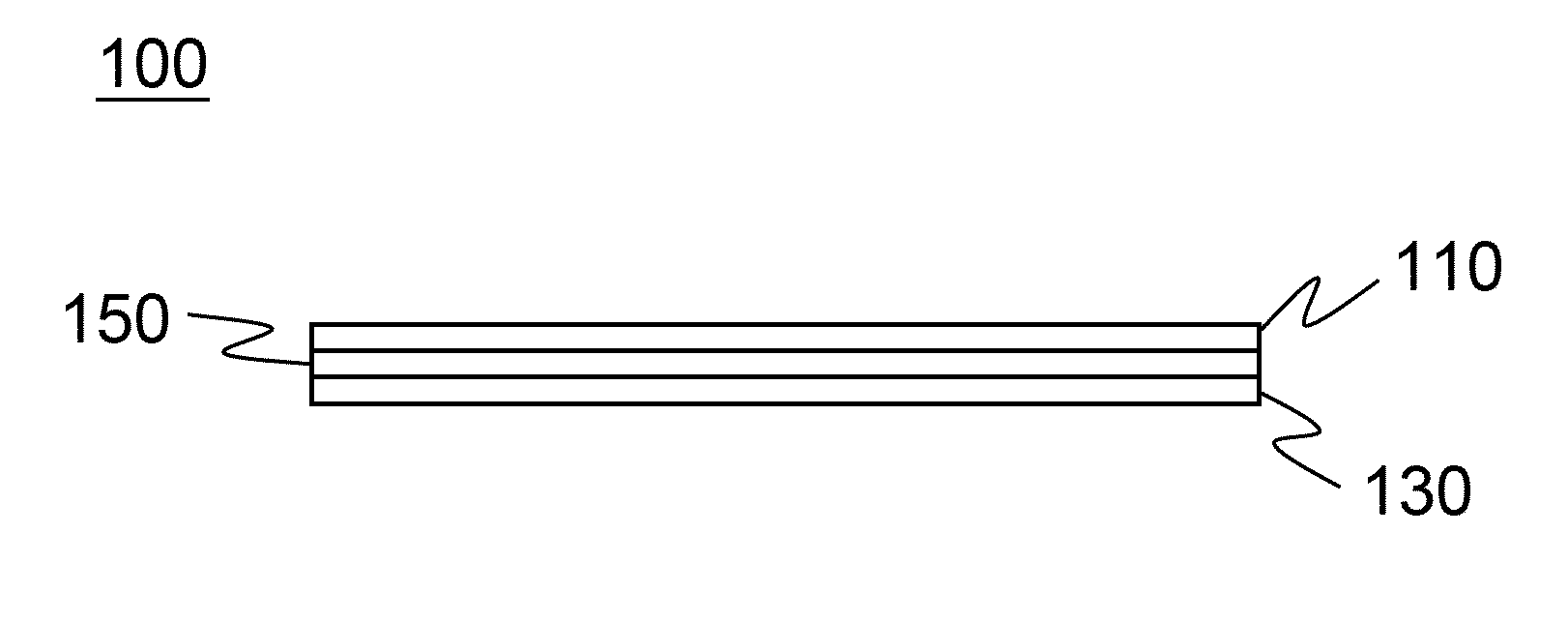
[0059]FIG. 1 shows a light uniformization structure according to an embodiment of the disclosure.

[0060]Referring to FIG. 1, a light uniformization structure 100 comprises two microstructure films 110, 130 and a spacer layer 150. The microstruct...


PUM


Abstract

A light uniformization structure and light emitting module is related to a light uniformization structure including a first material layer having a plurality of microstructures in a surface thereof, a second material layer having a plurality of microstructures in a surface thereof, and a spacer layer. The spacer layer is located between the first material layer and the second material layer, and a refractive index of the spacer layer is smaller than a refractive index of the first material layer and a refractive index of the second material layer.

Description

CROSS-REFERENCE TO RELATED APPLICATIONS[0001]This non-provisional application claims priority under 35 U.S.C. §119(a) on Patent Application No(s). 098141820 filed in Taiwan, R.O.C. on Dec. 8, 2009, and Patent Application No. 099138708 filed in Taiwan, R.O.C. on Nov. 10, 2010, as well as is a Continuation-in-part application of U.S. application Ser. No. 12 / 708,147, filed on Feb. 18, 2010, the entire contents of which are hereby incorporated by reference.BACKGROUND[0002]1. Field of the Disclosure[0003]The disclosure relates to a light source module, and more particularly to a light uniformization structure and a light emitting module.[0004]2. Related Art[0005]With the advantages of small volume, low power consumption, and long service life, the light emitting diode (LED) is the most effective among all other novel light emitting elements in terms of energy saving and carbon reduction. In recent years, the LED has been widely applied to illumination devices. Moreover, with increasing a...

Claims


Application Information

Patent Timeline
IPC IPC(8): F21V5/00
CPCF21V5/007F21V5/02F21Y2101/02G02B27/0961F21Y2105/001G02B27/0927F21Y2103/003F21Y2105/10F21Y2103/10F21Y2115/10
Inventor LIN, HUI HSIUNGLIAO, CHI HUNGYANG, WEN HSUNHSUEH, HAN-TSUNG
Owner IND TECH RES INST
Why Eureka
Try Eureka