Startup Circuit and Power Converter Employing the Same

a technology of start-up circuit and power converter, which is applied in the direction of power conversion systems, electrical apparatus, etc., can solve the problems of high-voltage switch requirements, significant power dissipation, and relatively high cost, and achieve the effect of reducing power dissipation

Active Publication Date: 2011-06-09
POWER SYST TECH
View PDF103 Cites 52 Cited by
  • Summary
  • Abstract
  • Description
  • Claims
  • Application Information

AI Technical Summary

Problems solved by technology

Thus, the input power required to start the power converter may approach 0.5 watt or more, which represents a significant level of power dissipation.
To switch off the startup current, a high voltage switch is required, which can be relatively expensive.
Thus, light-load and no-load power losses, while relatively small, have now become substantial hindrances to improving power converter efficiency as industry requirements become stricter each year.
Thus, despite the development of numerous strategies to reduce power losses of power adapters, no satisfactory strategy has emerged to provide substantial reduction of power dissipation while the adapter provides minimal or no power to a load.

Method used


Image

  • Startup Circuit and Power Converter Employing the Same
  • Startup Circuit and Power Converter Employing the Same
  • Startup Circuit and Power Converter Employing the Same

Examples


Embodiment Construction

[0013]The making and using of the present exemplary embodiments are discussed in detail below. It should be appreciated, however, that the present invention provides many applicable inventive concepts that can be embodied in a wide variety of specific contexts. The specific embodiments discussed are merely illustrative of specific ways to make and use the invention, and do not limit the scope of the invention.

[0014]The present invention will be described with respect to exemplary embodiments in a specific context, namely, a startup circuit configured to provide reduced power dissipation for a power converter. While the principles of the present invention will be described in the environment of a power converter, any application that may benefit from a power conversion device including a motor drive or a power amplifier is well within the broad scope of the present invention.

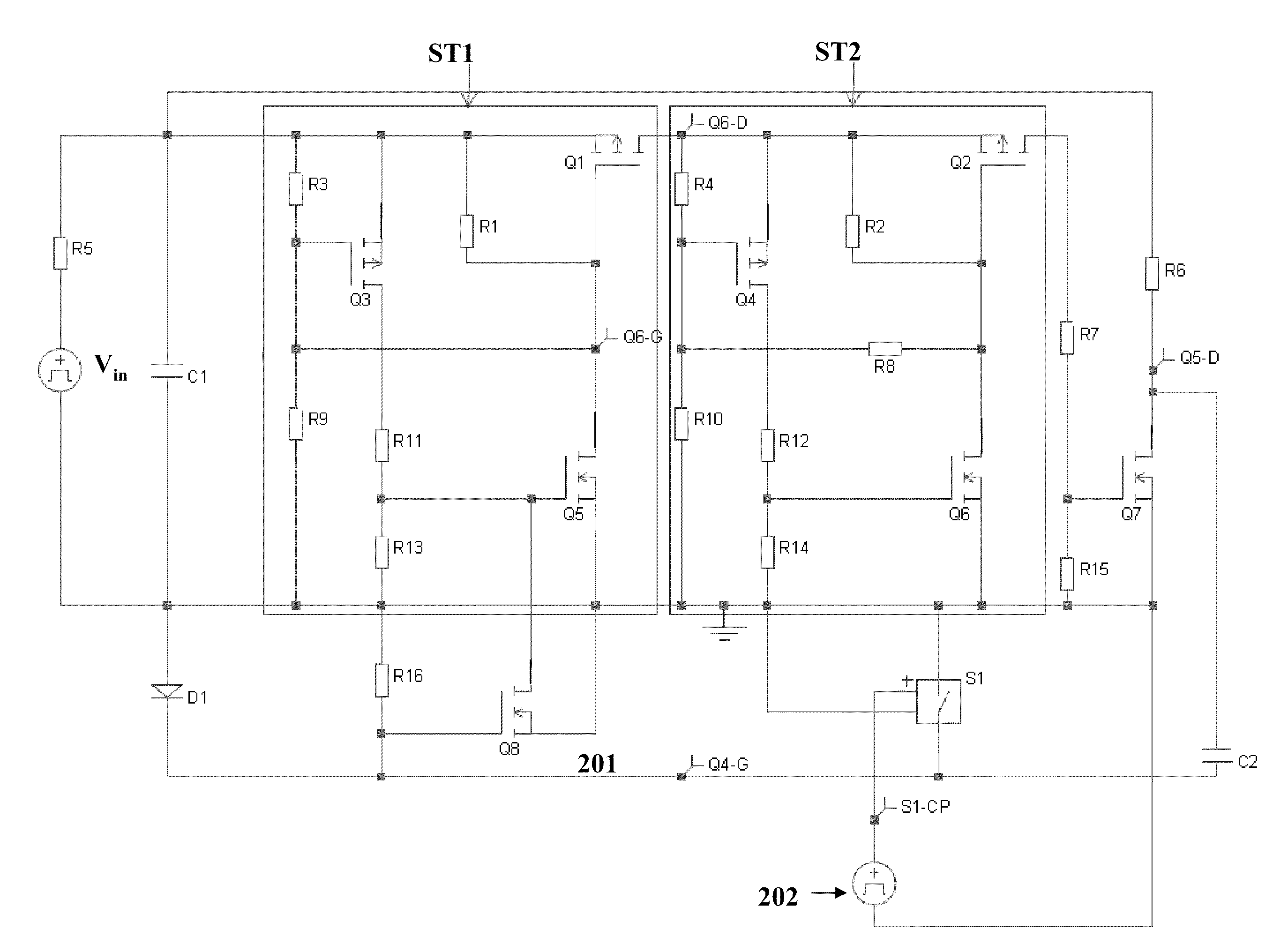
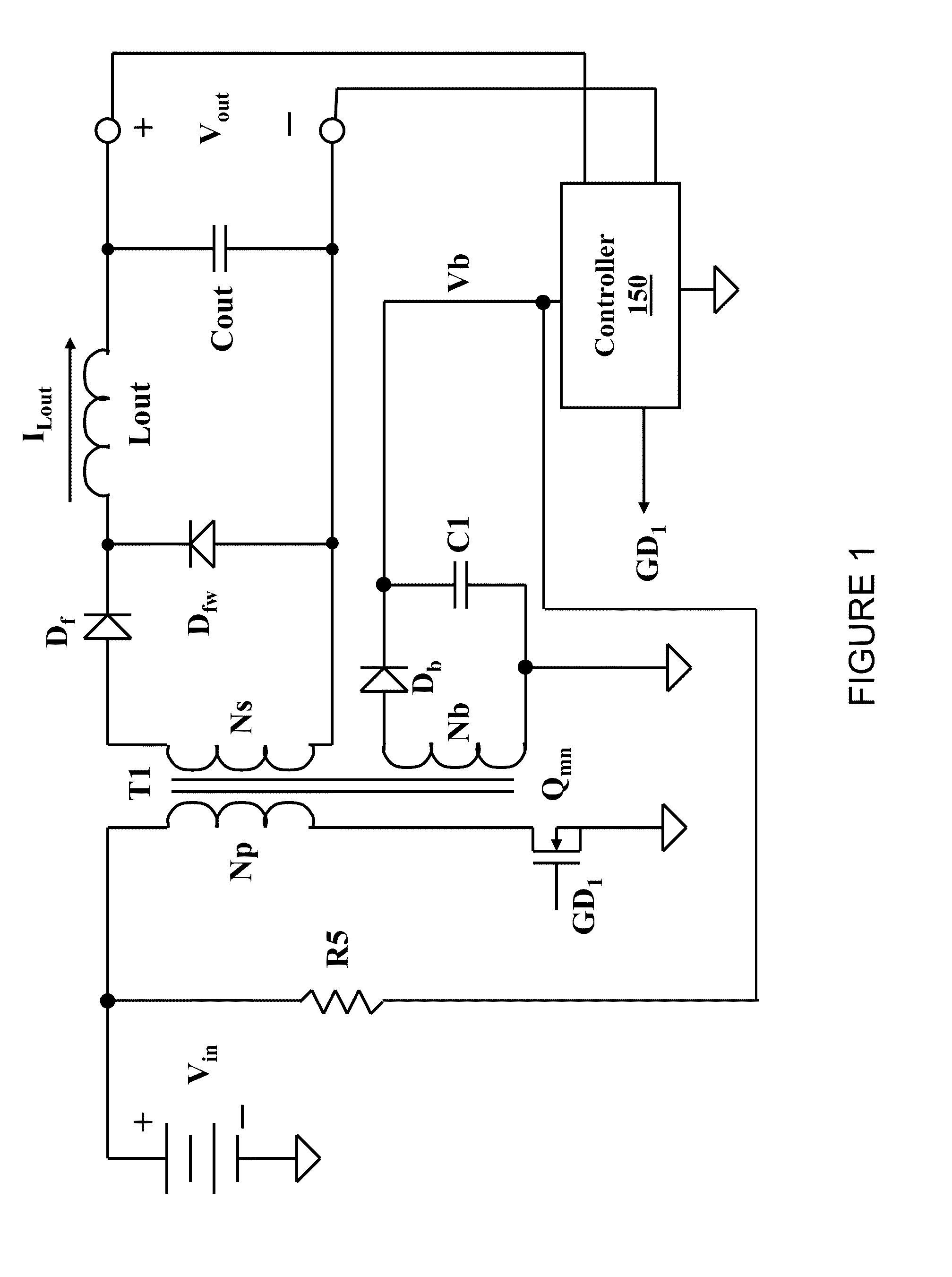
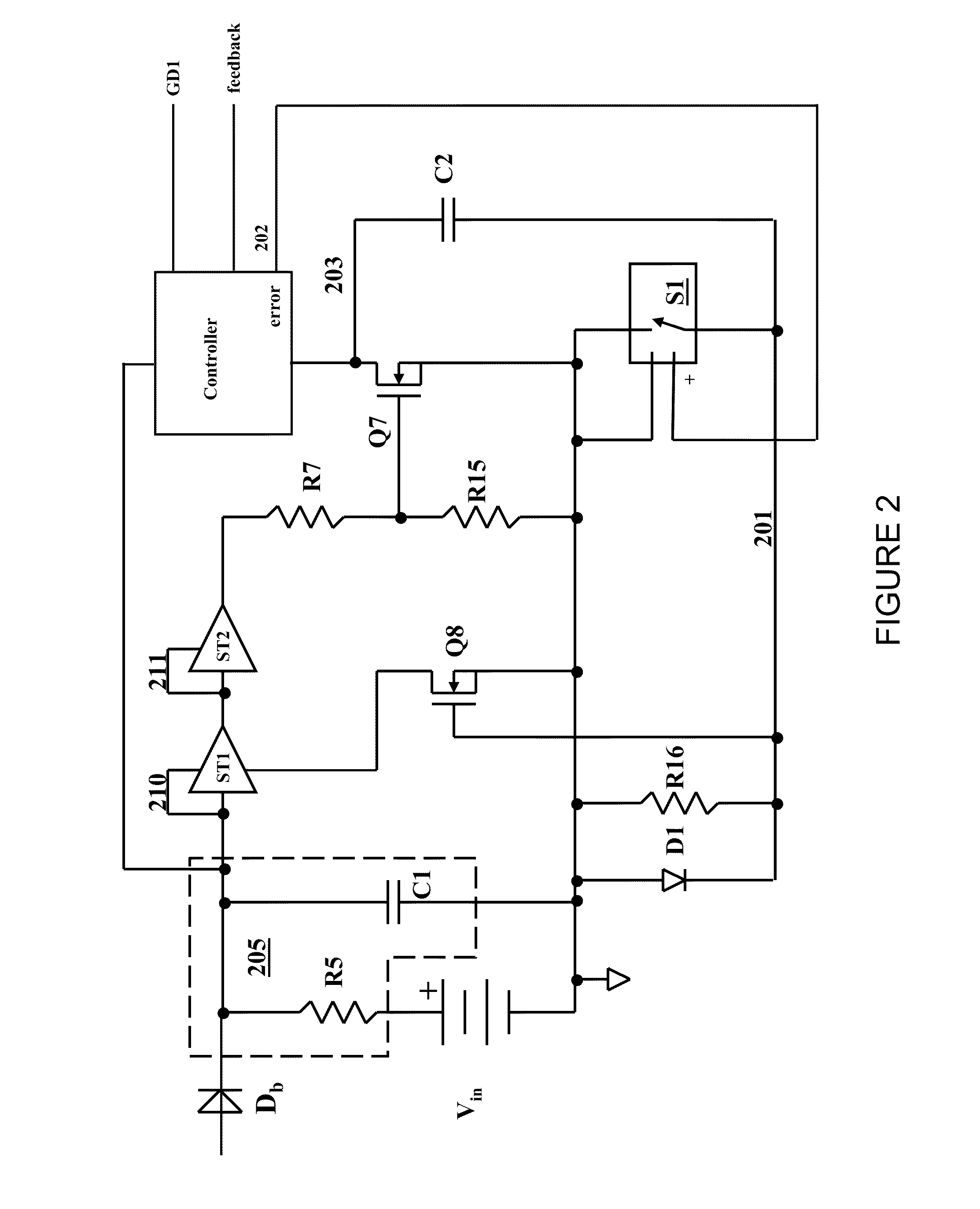
[0015]Turning now to FIG. 1, illustrated is a schematic diagram of an embodiment of portions of a power conver...


PUM


Abstract

A startup circuit with reduced power dissipation, method of operating the same and a power converter employing the startup circuit. In one embodiment, the startup circuit for a controller includes a charge accumulation circuit having a resistor series-coupled to a capacitor and a first Schmitt trigger having an input coupled to the capacitor. The startup circuit also includes a second Schmitt trigger having an input coupled to an output of the first Schmitt trigger and configured to provide a bias voltage for the controller via the capacitor when an input voltage thereto exceeds a trip voltage.

Description

TECHNICAL FIELD[0001]The present invention is directed, in general, to power electronics and, more specifically, to a startup circuit with reduced power dissipation and method of operating the same.BACKGROUND[0002]A switched-mode power converter (also referred to as a “power converter” or “regulator”) is a power supply or power processing circuit that converts an input voltage waveform into a specified output voltage waveform. DC-DC power converters convert a direct current (“dc”) input voltage that may be derived from an alternating current (“ac”) source by rectification into a dc output voltage. Controllers associated with the power converters manage an operation thereof by controlling conduction periods of power switches employed therein. Some power converters include a controller coupled between an input and output of the power converter in a feedback loop configuration (also referred to as a “control loop” or “closed control loop”) to regulate an output characteristic of the po...

Claims


Application Information

Patent Timeline
Patent Type & Authority Applications(United States)
IPC IPC(8): H02M1/00
CPCH02M1/36
Inventor BERGHEGGER, RALF SCHROEDER GENANNT
Owner POWER SYST TECH
Why Eureka
Try Eureka