Oscillation circuit and electronic equipment comprising semiconductor integrated device with clock function including the oscillation circuit

a technology of oscillating circuit and integrated device, which is applied in the field of oscillating circuit and electronic equipment comprising semiconductor integrated devices, can solve the problems of battery capacity decline, difficulty in implementing a sufficient decrease of power consumption required for electronic equipment, and critical power consumption drop, so as to achieve the effect of reducing current consumption and power consumption

Inactive Publication Date: 2005-01-27
ROHM CO LTD
View PDF1 Cites 18 Cited by
  • Summary
  • Abstract
  • Description
  • Claims
  • Application Information

AI Technical Summary

Benefits of technology

[0013] In the oscillation circuit according to the present invention, the Schmitt trigger circuit connected to the constant current source shapes the waveform of the output of

Problems solved by technology

As described above, a decrease of power consumption is a critical issue, for which many measures have been taken.
However it is difficult to implement a sufficient decrease of power consumption required for electronic equipment, even if such an above

Method used


Image

  • Oscillation circuit and electronic equipment comprising semiconductor integrated device with clock function including the oscillation circuit
  • Oscillation circuit and electronic equipment comprising semiconductor integrated device with clock function including the oscillation circuit
  • Oscillation circuit and electronic equipment comprising semiconductor integrated device with clock function including the oscillation circuit

Examples


Embodiment Construction

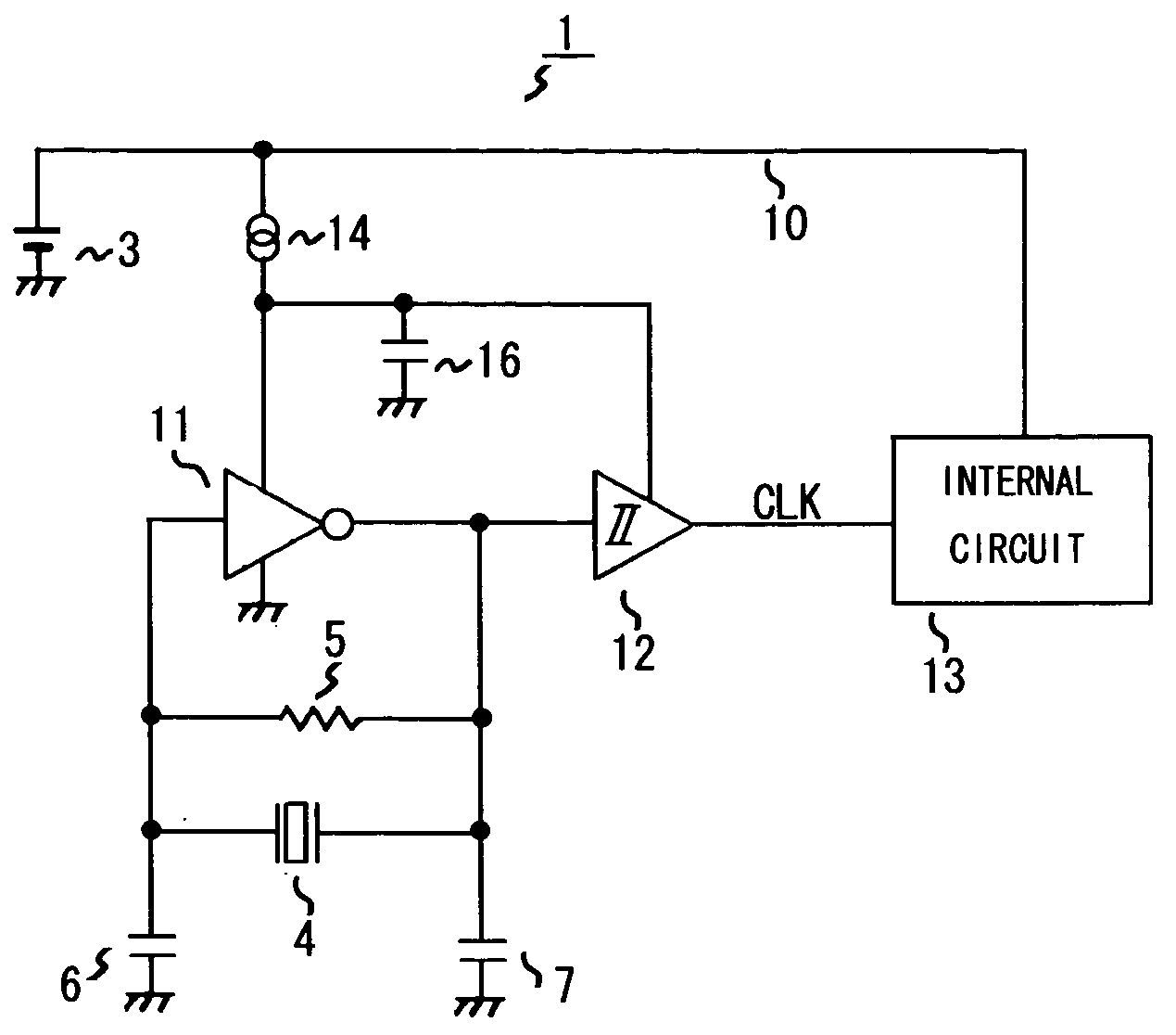
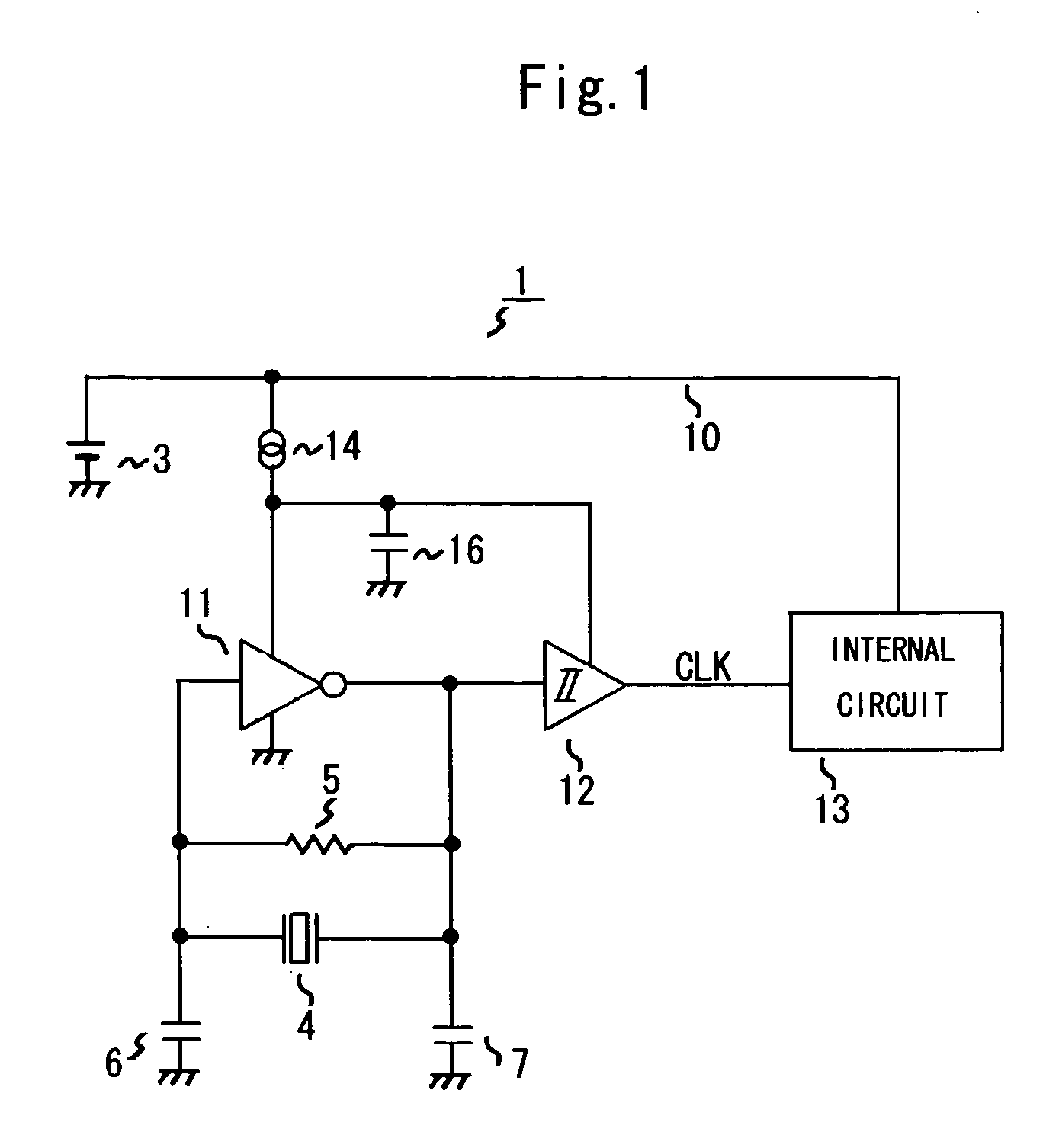
[0020] Embodiments of the present invention will now be described with reference to the accompanying drawings. FIG. 1 is a circuit diagram depicting the configuration of an oscillation circuit 1 according to an embodiment of the present invention.

[0021] This oscillation circuit 1 is comprised of a piezoelectric oscillator 4 for generating voltage that oscillates at a natural frequency, 32.768 KHz for example, an inverter 11 for amplifying this oscillation voltage, a Schmitt trigger circuit 12 for shaping the waveform of the output of the inverter 11, and a constant current source 14 which is connected to a power supply line 10 from a battery 3 and supplies current to the power supply of the inverter 11 and the Schmitt trigger circuit 12. Here a quartz oscillator is generally used since an accurate frequency is required for clock use.

[0022] The oscillation circuit 1 further comprises a feedback resistance 5 with high resistance value, which is disposed in parallel with the piezoele...


PUM


Abstract

The present invention provides an oscillation circuit which enables a further decrease of power consumption. The oscillation circuit comprises a piezoelectric oscillator, such as a quartz oscillator, for generating voltage that oscillates at a natural frequency, an inverter for amplifying this oscillation voltage, a Schmitt trigger circuit for shaping the waveform of the output of the inverter and outputting oscillation output signals, and a constant current source which is connected to a power supply line from a battery and supplies current to the power supply of the inverter and the Schmitt trigger circuit.

Description

BACKGROUND OF THE INVENTION [0001] 1. Field of the Invention [0002] The present invention relates to an oscillation circuit using a piezoelectric oscillator and electronic equipment comprising a semiconductor integrated device with a clock function including the oscillation circuit. [0003] 2. Description of the Related Art [0004] There are many conventional electronic equipment, such as digital cameras, that have a clock function to display or record time in real-time. In order to implement the clock function, it is common to comprise an oscillation circuit for a clock and count time by the constant oscillation of the oscillation circuit even if the electronic equipment isn't used. Therefore if the electronic equipment is for portable use, low power consumption is demanded for the oscillation circuit so that the battery to supply power does not run down easily. [0005] The oscillation circuit shown in FIG. 4 is a conventional oscillation circuit where a decrease of power consumption ...

Claims


Application Information

Patent Timeline
IPC IPC(8): G04G3/00H03B5/32H03K3/012H03K3/03H03K3/353
CPCH03K3/0307H03K3/012H03B5/32
Inventor ASHIDA, HIROYUKITSUJI, YASUHIKO
Owner ROHM CO LTD
Why Eureka
Try Eureka