UVLO circuit

An undervoltage lockout and circuit technology, applied in the field of undervoltage lockout, can solve the problems of large occupation area, slow response time, and many components, and achieve the effect of small occupation area, reduced components, and reduced response time.

Active Publication Date: 2010-09-08
NINGBO SEMICON INT CORP
View PDF2 Cites 19 Cited by
  • Summary
  • Abstract
  • Description
  • Claims
  • Application Information

AI Technical Summary

Problems solved by technology

Since this kind of undervoltage lockout circuit is mainly composed of a comparator and a reference voltage source, it uses more components, occupies a larger area, and has a slower response time.

Method used


Image

  • UVLO circuit
  • UVLO circuit
  • UVLO circuit

Examples


Embodiment 1

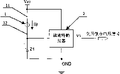
[0019] An undervoltage lockout circuit proposed by the present invention mainly utilizes the leading edge trigger level V of the Schmitt trigger + and trailing edge trigger level V - , leading edge trigger level V + and trailing edge trigger level V - They can be set separately by adjusting the parameters of the corresponding devices in the Schmitt trigger. will be the leading edge trigger level V + As the turn-on voltage of the undervoltage lockout circuit of the present invention, the trailing edge trigger level V - As the shutdown voltage of the undervoltage lockout circuit of the present invention; or, the leading edge trigger level V + As the shutdown voltage of the undervoltage lockout circuit of the present invention, the trailing edge trigger level V - As the turn-on voltage of the undervoltage lockout circuit of the present invention, the basic functions of the undervoltage lockout circuit of the present invention are realized. Here, in order to obtain the hyste...

Embodiment 2

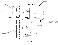
[0026] Such as Figure 4 and Figure 5 As shown, this embodiment is basically the same as Embodiment 1, the only difference is that a logic circuit 3 is connected to the output end of the Schmitt trigger 2, and the input end of the logic circuit 3 is connected to the output end of the Schmitt trigger 2 After being connected with each other, the voltage signal output by the output terminal of the Schmitt trigger 2 is processed by the logic circuit 3, and the output terminal of the logic circuit 3 outputs the undervoltage lockout voltage signal (waveform) required by the subsequent circuit.

[0027] In this specific embodiment, the logic circuit 3 is mainly composed of an inverter U1, the output terminal of the Schmitt trigger 2 is connected to the input terminal of the inverter U1, and the output terminal of the inverter U1 outputs an undervoltage lockout Save the voltage signal. Here, the inverter U1 is mainly used to sort out the voltage signal output by the output terminal...


PUM


Abstract

The invention discloses a UVLO (under-voltage lockout) circuit mainly comprising a Schmitt trigger, a Zener diode and a current bios. Being based on the relative change between the voltage of a power source and the stabilized voltage of the cathode terminal of the Zener diode, the UVLO circuit can convert the conventional Schmitt trigger from the toggle caused by the change in the input voltage signal to the toggle caused by change in the voltage of the power source, to which the Schmitt is connected, thus achieving the effect of UVLO on the voltage of the power source. The UVLO circuit is dispensed with the extra reference voltage source and a comparator, thus greatly simplifying the components and circuit structure, ensuring that the occupied area of the UVLO circuit is smaller and further making great improvement on the response time thereof at the same time.

Description

technical field [0001] The invention relates to an undervoltage lockout technology for a startup circuit in an analog integrated circuit, in particular to an undervoltage lockout circuit. Background technique [0002] When the power chip is powered on and started, the power supply will charge the power chip through the equivalent resistance and capacitance of the input terminal of the power chip, so that the power supply voltage of the power chip rises steadily, until the power supply voltage rises to the turn-on voltage of the power chip, the power chip starts to work normally Work. However, when the load current of the system using the power chip is large, the power supply voltage of the power chip may be pulled down below the turn-on voltage of the power chip, so that the system will be turned off as soon as it is turned on. In order to ensure that the power chip normally enters the start-up state and works stably, and also in order that the fluctuation of the power supp...

Claims


Application Information

Patent Timeline
Patent Type & Authority Applications(China)
IPC IPC(8): H02M1/32
Inventor 曾强
Owner NINGBO SEMICON INT CORP
Why Eureka
Try Eureka