Machine shaking laser gyroscope shaking demodulating device and demodulating method based on FPGA

A technology of machine-shaking laser gyroscope and demodulation device, applied in Sagnac effect gyroscope and other directions, can solve the problems of sampling counting error, impossible complete synchronization, counting error and so on

Inactive Publication Date: 2008-10-08
HARBIN ENG UNIV
View PDF0 Cites 18 Cited by
  • Summary
  • Abstract
  • Description
  • Claims
  • Application Information

AI Technical Summary

Problems solved by technology

[0004] 1. The sampling period is difficult to be strictly consistent with the actual frequency bias commutation period of the laser gyroscope, resulting in sampling and counting errors;
[0005] 2. In the strapdown inertial navigation system, timing sampling and navigation calculation are required, but the timing sampling period and the actual jitter commutation period of the laser gyroscope cannot be completely synchronized. Even if the recursive difference algorithm is used, there are also counting errors;
[0006] 3. It cannot effectively eliminate the random jitter signal and noise caused by other factors in the jitter-biased laser gyro

Method used


Image

  • Machine shaking laser gyroscope shaking demodulating device and demodulating method based on FPGA
  • Machine shaking laser gyroscope shaking demodulating device and demodulating method based on FPGA
  • Machine shaking laser gyroscope shaking demodulating device and demodulating method based on FPGA

Examples


Embodiment Construction

[0033] The present invention is described in more detail below in conjunction with accompanying drawing example:

[0034] The present invention is based on the digital filtering method of FPGA, and this demodulation method is applied in concrete demodulation device, in the present invention, the realization of filter is the key of whole demodulation scheme, has carried out concrete static experiment at last, And analyze the experimental data, it will be further described in detail in three parts combined with the accompanying drawings.

[0035] 1. FPGA implementation of demodulation method

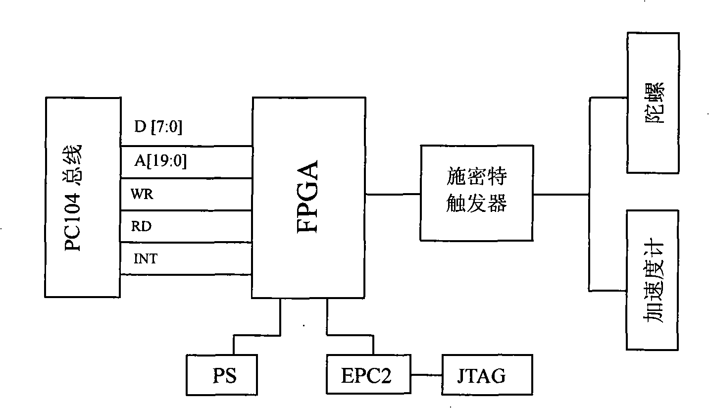
[0036] The data acquisition circuit of the entire laser gyroscope includes two parts: reversible counting and digital filtering, such as Figure 7 shown. The two signals SIN and COS output by the laser gyro are reversibly counted by the reversible counting unit, then sent to the register for storage, and then sampled at 1kHz, sent to the FIR low-pass filter, and then sent to the anti-ali...


PUM


Abstract

The invention provides a trembling laser spinning trembling demodulating device based on the FPGA. The device is composed of FPGA and the Schmitt trigger respectively connected to the FPGA and the PC/104 and the collocation of the FPGA; in the reverse counting and the digital filter compose the data collecting circuit; the laser spinning outputs two beams of the signals of SIN, COS inputs the reverse counting unit for the reverse counting and then delivering to the register; sampling by the 1kHz, delivering the FIR low pass filter; after the filtering, delivering the anti-overlapping filter to process the descending sampling. The invention processes the trembling laser spinning trembling demodulation via the digital filtering method which can makeup the defect of the periodical sampling; delivering the anti-overlapping filter to process the descending sampling; the invention can effectively eliminate the noise caused by the other factors and the random trebling signal of the bias frequency laser spin and saves the precious design time.

Description

(1) Technical field [0001] The invention relates to a control device and a control method of a laser gyroscope, in particular to a jitter demodulation device and a demodulation method of a mechanically shaken laser gyroscope. (2) Background technology [0002] The laser gyroscope is the only non-electromechanical medium-high precision inertial sensitive instrument that has really achieved fruitful practical applications in the field of inertial technology. The laser gyroscope uses the Sagnac effect of the ring light path, that is, in the ring light path of any geometric shape, the phase difference (or optical path difference) of the two beams of light running relatively in the clockwise and counterclockwise directions is the same as that of the ring light path relative to The rotation rate of the inertial space is linear. The practical laser gyroscope mainly adopts the mechanical jitter bias frequency scheme to solve the problem of latch-up effect. [0003] For the two-fre...

Claims


Application Information

Patent Timeline
Patent Type & Authority Applications(China)
IPC IPC(8): G01C19/70
Inventor 孙枫陈世同高伟奔粤阳徐博于强高洪涛周广涛吴磊程建华
Owner HARBIN ENG UNIV
Why Eureka
Try Eureka