Driving circuit for LED

a driving circuit and led technology, applied in the direction of pulse manipulation, pulse technique, instruments, etc., can solve the problems of increasing the difficulty in designing the driving circuit, the input signal of the control module of the driving circuit for the led will suffer an unstable state of severe up-and-down vibration, and the difficulty of the driving circuit, so as to achieve the effect of driving the led simply and efficiently

Inactive Publication Date: 2012-08-30
HANERGY TECH
View PDF13 Cites 19 Cited by
  • Summary
  • Abstract
  • Description
  • Claims
  • Application Information

AI Technical Summary

Benefits of technology

[0007]The present invention provides a method for driving the LED, which can drive the LED simply and efficiently, and is quite beneficial for the popularization of the LED.

Problems solved by technology

LEDs connected in series also raise the variation range of the driving voltage, which increases the difficulty in designing the driving circuit.
However, during the period when the energy of the input wave is decreased, the input signal of the control module of the driving circuit for the LED will suffer an unstable status of severe up-and-down vibration.
This is difficult for the signal processing elements in the control module of the driving circuit for the LED to perform relevant operations to generate the control signal for driving the LED.
Therefore, it is difficult for the driving circuit for the LED to provide a stable current to the LED in response to different topologies.

Method used


Image

  • Driving circuit for LED
  • Driving circuit for LED
  • Driving circuit for LED

Examples


first embodiment

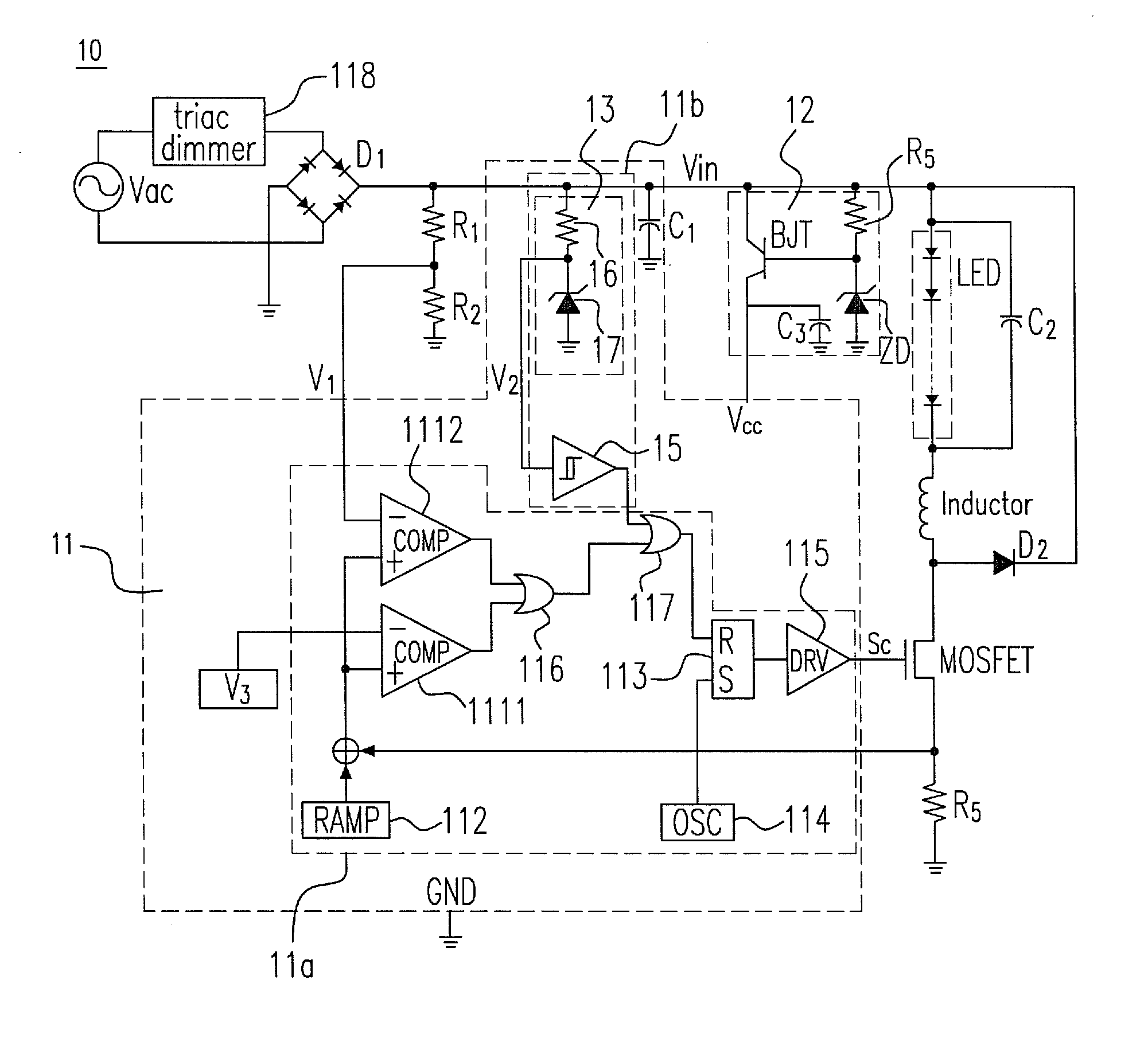
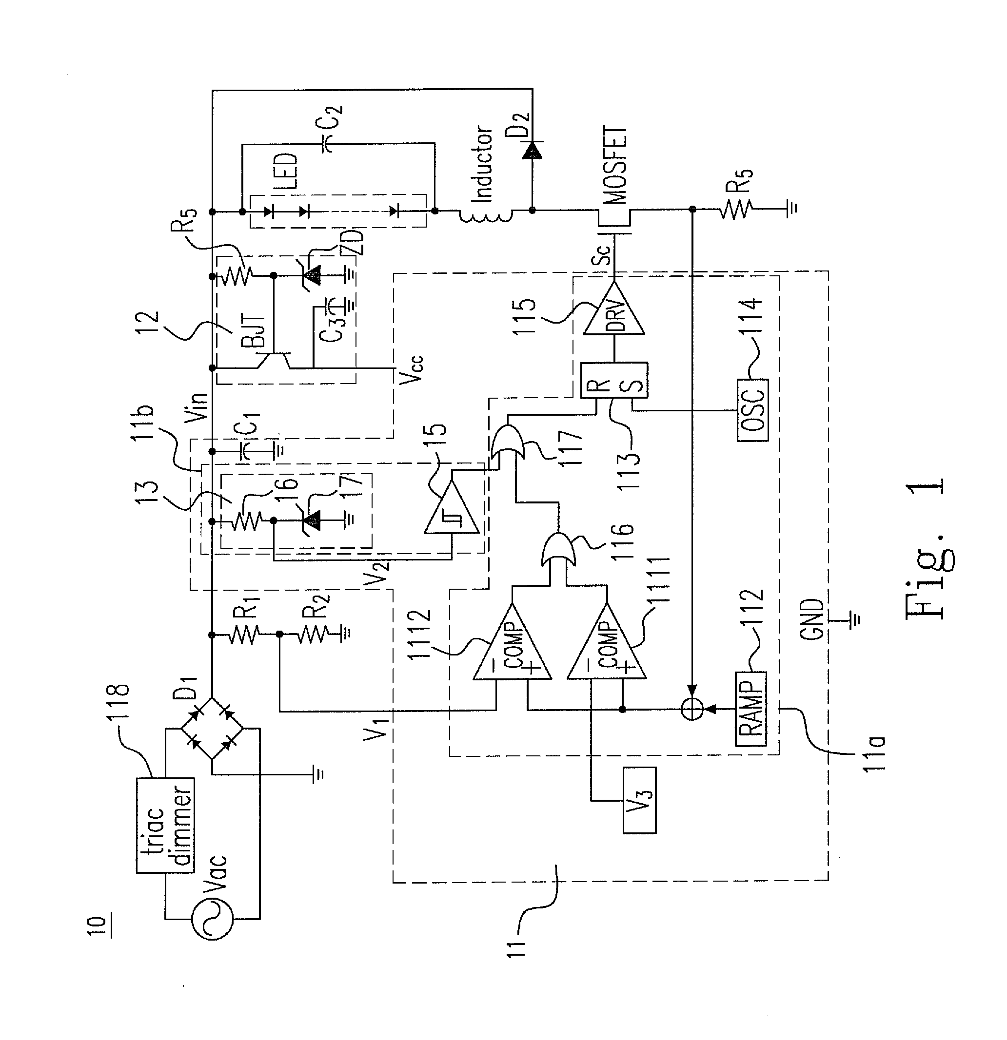
[0018]Please refer to FIG. 1, which shows a driving circuit 10 for the LED according to the present invention. The driving circuit 10 includes a control module 11. The control module 11 includes a power correction module 11a and a pulse width modulation module 11b. The power correction module 11a provides a control signal Sc to adjust the current flowing through a load. The power correction module 11a includes a first comparator 1111, a second comparator 1112, a ramp signal 112, an RS flip-flop 113, an oscillator 114, a driving gate 115, a first OR gate 116 and a second OR gate 117. The pulse width modulation module 11b is in cooperation with the power correction module 11a to modulate the control signal Sc. The pulse width modulation module 11b includes a voltage providing unit 13 and a Schmitt trigger circuit 15. The voltage providing unit 13 provides a pulse width modulation signal V2. The driving circuit 10 further includes a voltage clamping module 12 for providing a power volt...

second embodiment

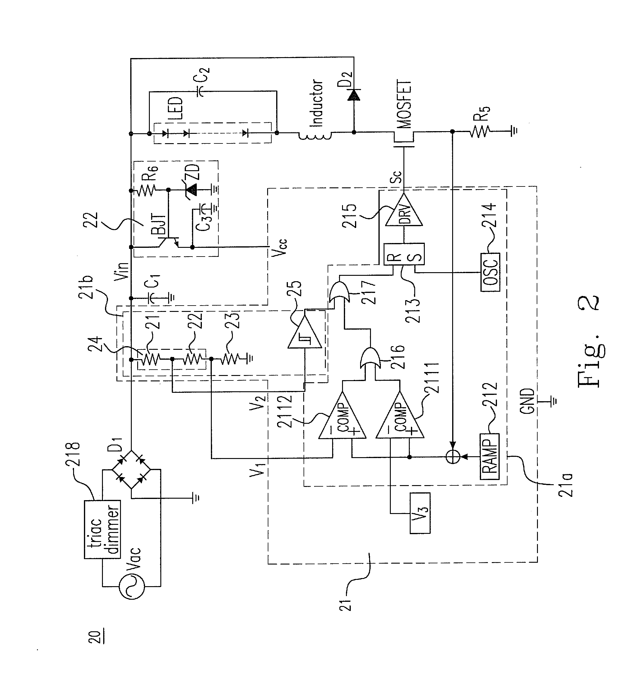
[0020]Please refer to FIG. 2, which shows a driving circuit 20 for the LED according to the present invention. The driving circuit 20 includes a control module 21. The control module 21 includes a power correction module 21a and a pulse width modulation module 21b. The power correction module 21a provides a control signal Sc to adjust the current flowing through a load. The power correction module 21a includes a first comparator 2111, a second comparator 2112, a ramp signal 212, an RS flip-flop 213, an oscillator 214, a driving gate 215, a first OR gate 216 and a second OR gate 217. The pulse width modulation module 21b is in cooperation with the power correction module 21a to modulate the control signal Sc. The pulse width modulation module 21b includes a voltage providing unit 24 and a Schmitt trigger circuit 25. The voltage providing unit 24 provides a pulse width modulation signal V2. The driving circuit 20 further includes a voltage clamping module 22 for providing a power volt...

embodiment 1

[0029]2. The driving circuit of Embodiment 1, further comprising:[0030]a voltage clamping module providing a power voltage to the control module.

[0031]3. The driving circuit of any one of Embodiments 1-2, wherein the power correction module performs a power factor correction.

[0032]4. The driving circuit of any one of Embodiments 1-3, wherein the voltage providing unit comprises a first resistor, a second resistor and a third resistor which provide a first voltage and the pulse width modulation signal simultaneously.

[0033]5. The driving circuit of any one of Embodiments 1-4, wherein the voltage providing unit comprises a fourth resistor and a Zener diode which provide the pulse width modulation signal.

[0034]6. The driving circuit of any one of Embodiments 1-5, wherein the Schmitt trigger circuit receives the pulse width modulation signal.

[0035]7. The driving circuit of any one of Embodiments 1-6, further comprising:[0036]a triac dimmer adjusting a waveform of an input signal.

[0037]8....


PUM


Abstract

A driving circuit device for driving a load is provided. The driving circuit device includes a control module including a power correction module, and providing a control signal to adjust a current flowing through the load; and a pulse width modulation module being in cooperation with the power correction module to modulate the control signal, and including a voltage providing unit providing a pulse width modulation signal; and a Schmitt trigger circuit.

Description

CROSS-REFERENCE TO RELATED APPLICATION AND CLAIM OF PRIORITY[0001]The application claims the benefit of Taiwan Patent Application No. 100106295, filed on Feb. 24, 2011, in the Taiwan Intellectual Property Office, the disclosures of which are incorporated herein in their entirety by reference.FIELD OF THE INVENTION[0002]The present invention relates to a driving circuit, and more particularly to a driving circuit for an LED.BACKGROUND OF THE INVENTION[0003]The LED is a common electronic element. At first, the LED only serves as the red pilot lamp. Then, the yellow-light LED, the orange-light LED, the green-light LED and the blue-light LED appear, which greatly expand the application range of the LED. Currently, the LED can be used for the traffic light, the lamp, the wall lamp, the LED array fluorescent lamp, etc. When the current is very low (approximately smaller than 20 mA), it is simpler to drive a single LED or a plurality of LEDs. When the power loss is not considered, the driv...

Claims


Application Information

Patent Timeline
Patent Type & Authority Applications(United States)
IPC IPC(8): H05B41/282H03K3/017G05F1/10
CPCY02B20/346H05B37/0263H05B33/0845H05B33/0815H05B45/10H05B47/185Y02B20/30H05B45/375H05B45/3725
Inventor CHANG, CHARLESCHANG, RONALD
Owner HANERGY TECH
Why Eureka
Try Eureka