Apparatus for controlling multi-outlet power strip

a power strip and multi-outlet technology, applied in the direction of pulse technique, coupling device connection, instruments, etc., can solve the problems of large current transformers and expensive ones, and achieve the effect of reducing manufacturing costs and easy manufacturing

Inactive Publication Date: 2005-01-13
SHIM SANG KEUN
View PDF2 Cites 19 Cited by
  • Summary
  • Abstract
  • Description
  • Claims
  • Application Information

AI Technical Summary

Benefits of technology

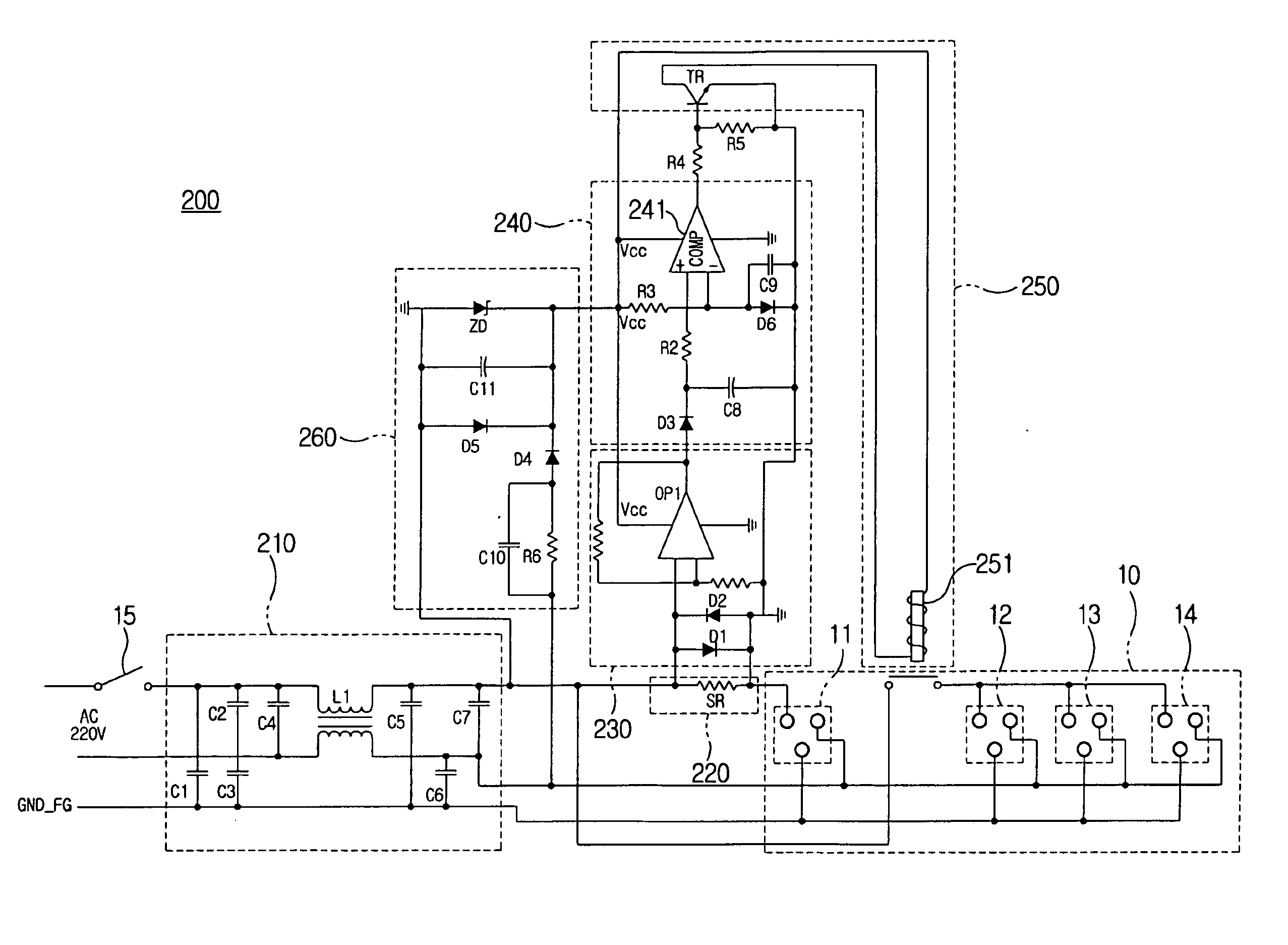
[0015] Accordingly, the present invention has been made in view of the above problems in the prior art, and it is an object of the present invention to provide to an apparatus for controlling a multi-outlet power strip, in which the above-described switch vibration can be avoided, and which can be easily fabricated along with reduction in the manufacturing cost.
[0023] Most preferably, the switch operator includes a first resistor having one terminal connected to an output terminal of the Schmitt trigger circuit, a second resistor having one terminal connected to another terminal of the first resistor, a transistor having a base connected to a junction between the another terminal of the first resistor and the one terminal of the second resistor, and a switch element connected to a collector of the transistor. Further, the switching element includes at least one of a relay, a solid state relay, a triac, and a thyristor. The apparatus further comprises a noise filter for preventing an externally unnecessary electric wave from being introduced into the multi-outlet power strip and preventing an unnecessary electric wave generated in the multi-outlet power strip from being exposed to an outside.

Problems solved by technology

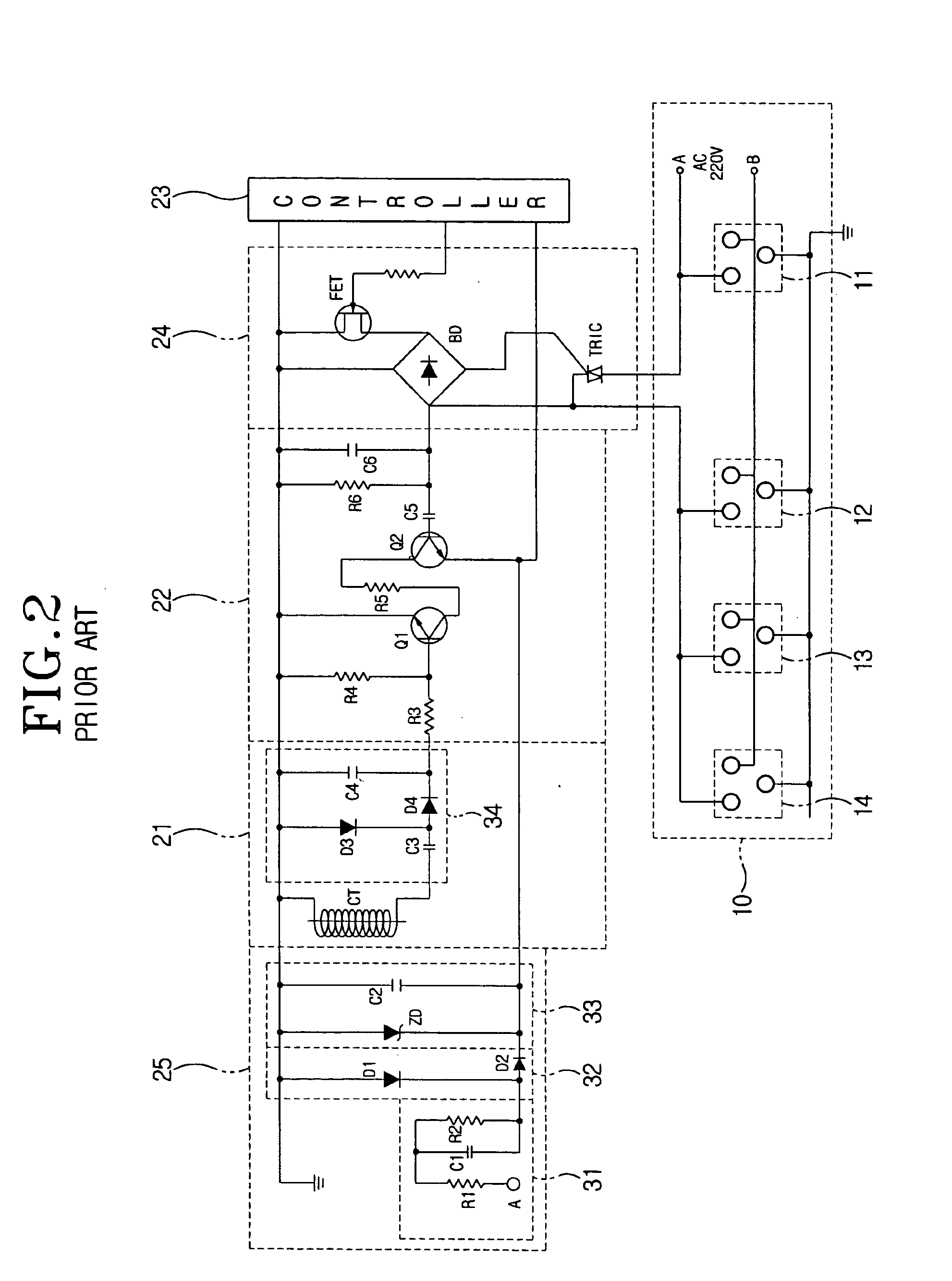
The above-described conventional multi-outlet control circuit, however, necessitates an expensive and large-sized current transformer for the current detector 21 to detect electric current flowing to the main outlet 11.

Method used


Image

  • Apparatus for controlling multi-outlet power strip
  • Apparatus for controlling multi-outlet power strip
  • Apparatus for controlling multi-outlet power strip

Examples


Embodiment Construction

[0031] Referring to the accompanying drawings, the preferred embodiments according to the present invention are described in detail hereafter. The same reference numerals used in different figures denote similar or identical components.

[0032]FIG. 3 illustrates a general computer system, in which peripheral devices are plugged to a multi-outlet power strip, along with a main computer. As shown in FIG. 3, the main computer 51 is used, generally together with a plurality of peripheral devices, for example, a monitor 52, a printer 53, a scanner 54, a speaker (not shown) and the like. An alternating current is supplied to the main computer 51 and the peripheral devices via a multi-outlet power strip 10, in which a plurality of outlets 11 to 14 are provided for the devices to be connected.

[0033] Therefore, users must use a switch 15 provided in the multi-outlet power strip 10 in order to cut off the electric power supplied to the peripheral devices, after finishing the use of the main c...


PUM


Abstract

An apparatus for controlling a multi-outlet power strip, in which the above-described switch vibration can be avoided, and which can be easily fabricated along with reduction in the manufacturing cost is provided. Detector detects electric current flowing through the main plug connector. Amplifier amplifies the electric current detected by the current detector to produce an amplified signal. Schmitt trigger circuit compares the amplified signal from the amplifier with a reference value, and outputs a control signal for a vibration prevention having a predetermined threshold voltage according to the compared result. Switch operator switches an electric power to the plurality of auxiliary connectors. Driver drives the detector, the amplifier, the Schmitt trigger circuit, and the switch operator.

Description

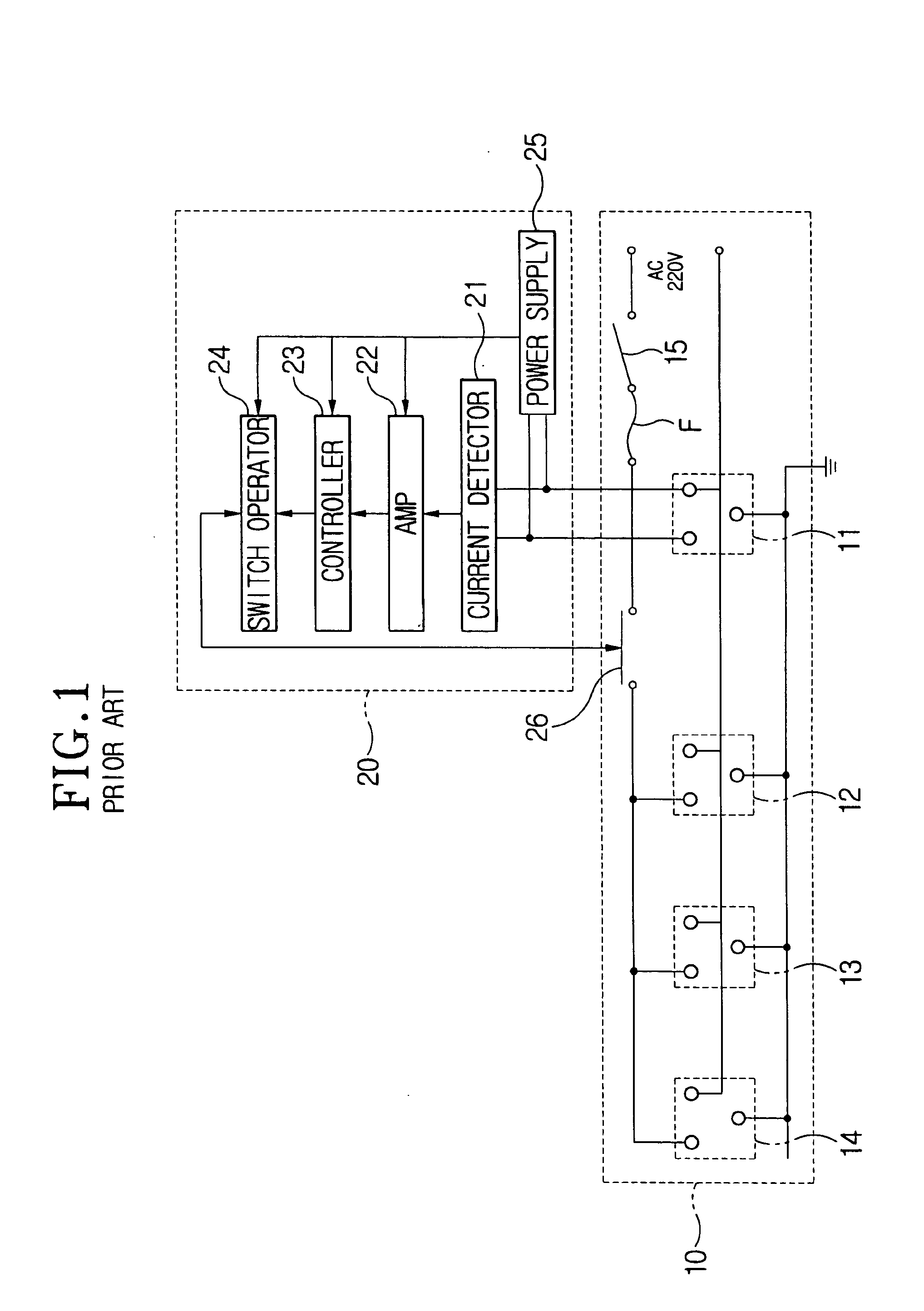
BACKGROUND OF THE INVENTION [0001] 1. Field of the Invention [0002] The present invention relates to an apparatus for controlling a multi-outlet power strip, particularly to such an apparatus which can be applied to an electrical wiring system having a multiple outlets to which plural electric devices are electrically connected. More particularly, in the present invention, by sensing the electric current flowing to a main device, the electric power supplied to other sub-devices can be automatically cut-off, depending on whether or not the main device is turned on. [0003] 2. Description of the Related Art [0004]FIG. 1 schematically shows the general concept of the multi-outlet control circuit, in which reference numeral 20 denotes a multi-outlet control circuit. As shown in FIG. 1, the multi-outlet power strip 10 is provided with a main outlet 11 to which the main computer is electrically connected, and plural sub-outlet 12 to 14 where various peripheral devices are electrically conn...

Claims


Application Information

Patent Timeline
Patent Type & Authority Applications(United States)
IPC IPC(8): H01R13/66G06F1/26H01R25/00H02H3/12H02J3/00H03K17/00
CPCG06F1/266H02H3/12G06F2200/261H01R25/00
Inventor SHIM, SANG-KEUN
Owner SHIM SANG KEUN
Why Eureka
Try Eureka