Radial roller bearing, in particular for the roller bearing mounting of shafts in internal combustion engines

a technology of internal combustion engines and roller bearings, which is applied in the direction of bearings, roller bearings, shafts, etc., can solve the problems of reducing the friction reduction effect, requiring further effort, and requiring a large amount of oil supply to the bearing points of internal combustion engines using the existing engine oil via supply lines and ducts provided specially for the purpose, so as to achieve simple and cost-effective

Inactive Publication Date: 2011-06-09
SCHAEFFLER TECH AG & CO KG
View PDF3 Cites 6 Cited by
  • Summary
  • Abstract
  • Description
  • Claims
  • Application Information

AI Technical Summary

Benefits of technology

[0007]Taking the discussed disadvantages of the known prior art as a starting point, the invention is therefore based on the object of designing a radial roller bearing, in parti

Problems solved by technology

It has however been found in practice that a pressurized oil supply to the bearing points in internal combustion engines using the existing engine oil via supply lines and ducts provided specially for the purpose is relatively complex and expensive and also necessitates a corresponding level of power of the existing oil pump, which must otherwise be exchanged for a more powerful version, and this involves further effort.
In the case of such a pressurized oil supply to the bearing points, there is likewise the risk of flooding of the roller bearing with lubricating oil, resulting in the desired

Method used


Image

  • Radial roller bearing, in particular for the roller bearing mounting of shafts in internal combustion engines
  • Radial roller bearing, in particular for the roller bearing mounting of shafts in internal combustion engines
  • Radial roller bearing, in particular for the roller bearing mounting of shafts in internal combustion engines

Examples


first embodiment

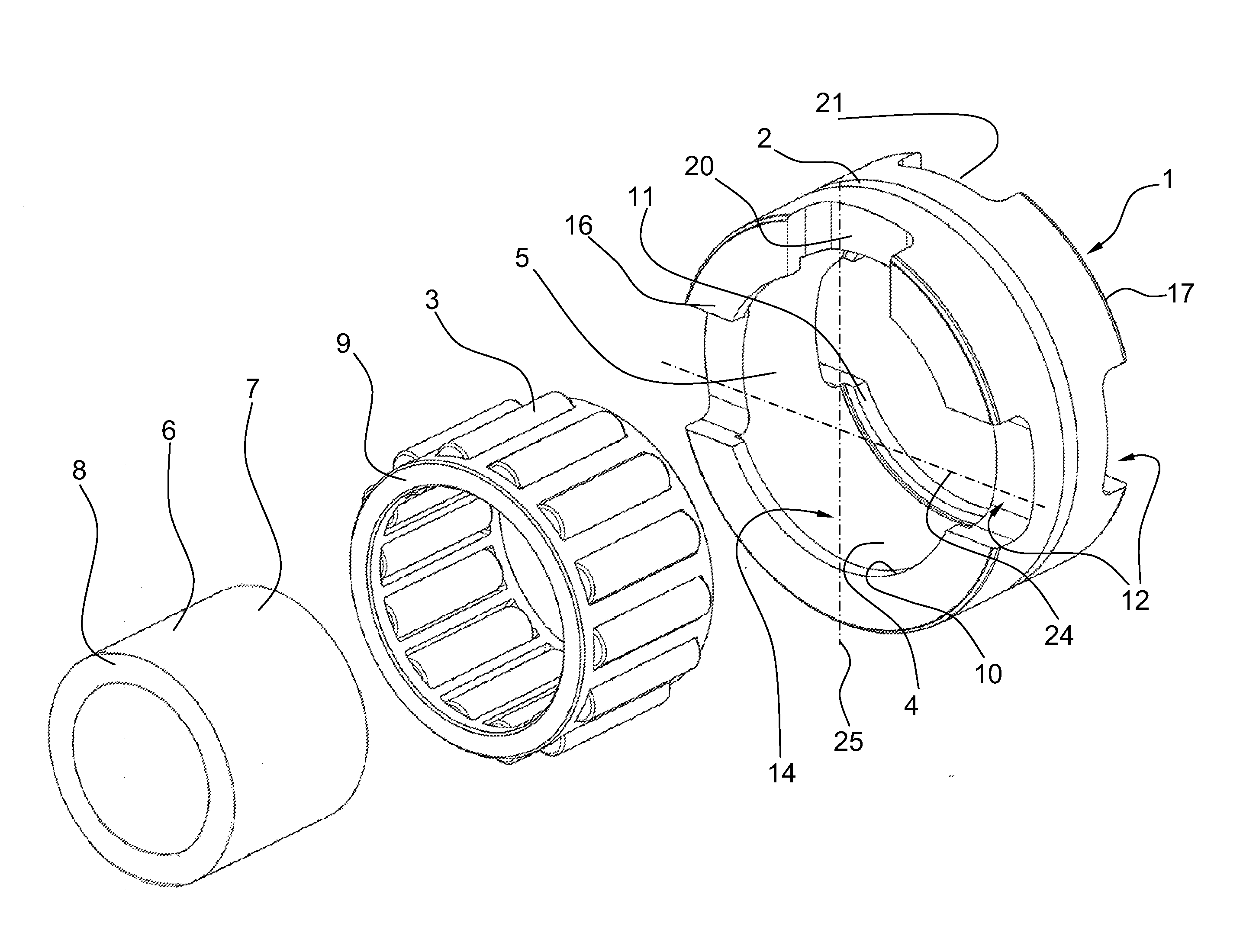
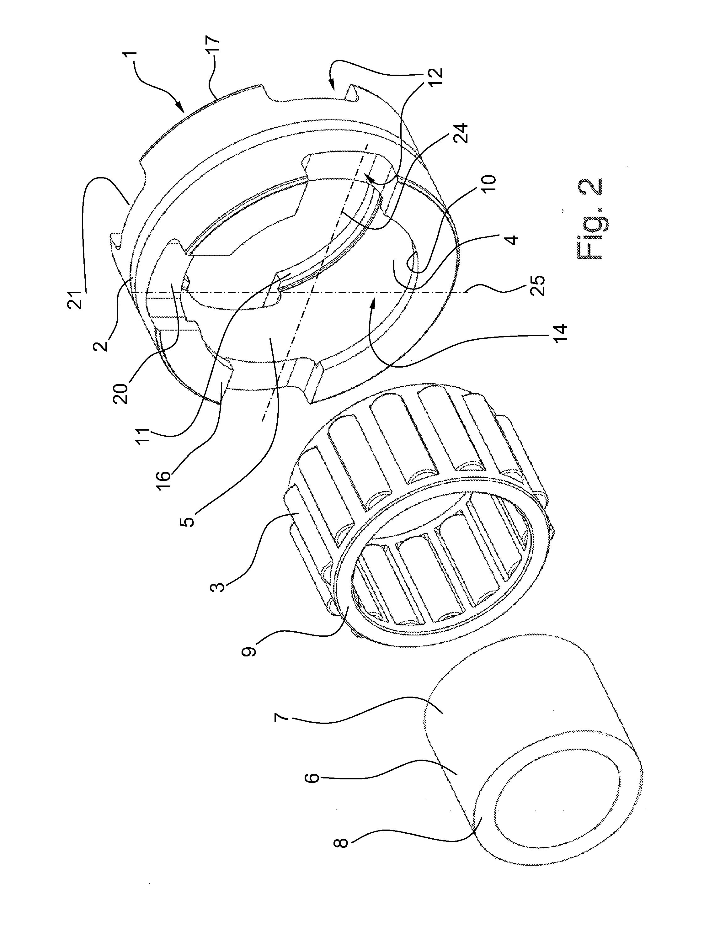
[0017]FIG. 2 shows an exploded illustration of a solid needle-roller bearing designed according to the invention;

second embodiment

[0018]FIG. 3 shows an exploded illustration of a solid needle-roller bearing designed according to the invention.

DETAILED DESCRIPTION OF THE DRAWINGS

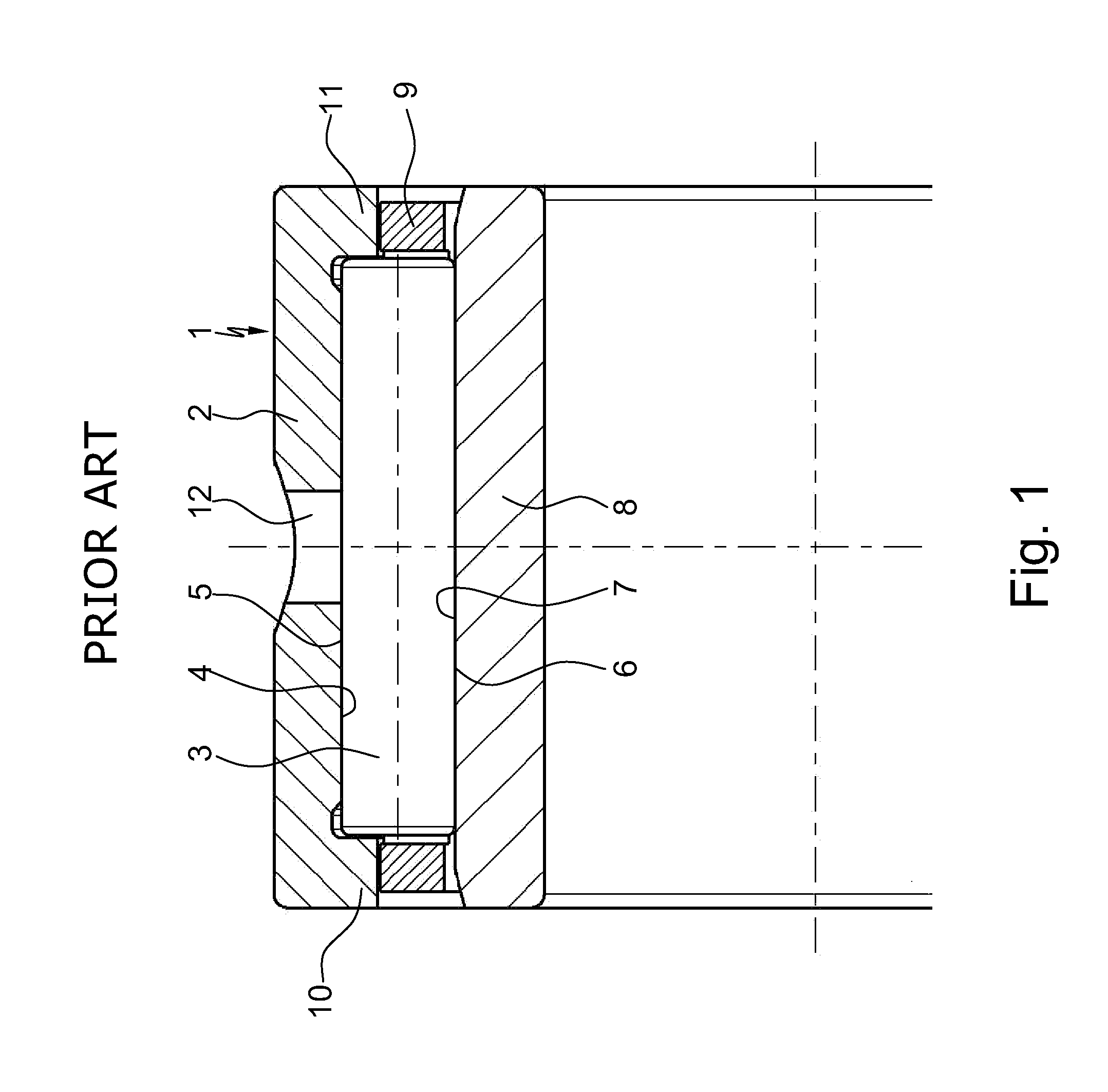
[0019]FIGS. 2 and 3 show in each case an exploded illustration of a radial roller bearing 1 which is designed as a solid needle-roller bearing and which is composed substantially of an outer bearing ring 2 and a multiplicity of cylindrical roller bodies 3 which roll on the inner lateral surface 5, which is formed as an outer raceway 4, of the outer bearing ring 2 and on the outer lateral surface 7, which is formed as an inner raceway 6, of an inner bearing ring 8, said cylindrical roller bodies 3 being held at uniform intervals with respect to one another in the circumferential direction by a bearing cage 9. Here, inwardly directed radial rims 10, 11 for the axial guidance of the roller bodies 3 are arranged on the outer bearing ring 2 axially at both sides, against which radial rims 10, 11 the roller bodies 3 run with their end surface...


PUM


Abstract

A radial roller bearing, which has an outer bearing ring and a multiplicity of cylindrical roller bodies which roll on the inner lateral surface of the outer bearing ring and the outer lateral surface of an inner bearing ring or a shaft. The roller bodies are held at uniform intervals by a bearing cage with inwardly directed radial rims for axial guidance. Lubricating openings, which lead from the outside into the bearing interior, supply lubricant, and are arranged on the outer or inner bearing ring axially at both sides. The lubricating openings are cutouts which are formed into one or both axial sides of the bearing rings, outside a load zone of the bearing rings, which extend into the outer or inner raceway of the roller bodies and in which the roller bodies are arranged so as to be partially freely accessible for receiving oil form the bearing surroundings.

Description

[0001]This application claims the priority of DE 10 2009 057 634.7 filed Dec. 9, 2009, which is incorporated by reference herein.DESCRIPTION[0002]1. Field of the Invention[0003]The invention relates to a radial roller bearing according to the precharacterizing features of Patent Claim 1, and can be applied particularly advantageously to needle-roller or cylindrical-roller bearings for the roller bearing mounting of shafts in internal combustion engines in an oil-mist-laden or spray-oil-laden environment.[0004]2. Background of the Invention[0005]To mount various shafts in internal combustion engines, such as crankshafts, camshafts and balancing shafts, use has increasingly been made recently of roller bearings instead of plain bearings in order to reduce friction, said roller bearings usually being formed by radial roller bearings. Aside from cylindrical-roller bearings and needle sleeves and needle bushes, solid needle-roller bearings have proven to be most suitable here, because th...

Claims


Application Information

Patent Timeline
IPC IPC(8): F16C33/66F16C19/46F16C19/26
CPCF16C9/02F16C2360/22F16C33/6659F16C33/58F16C19/46
Inventor SOLFRANK, PETERSEITZ, JOACHIMULLMANN, PATRICK
Owner SCHAEFFLER TECH AG & CO KG
Why Eureka
Try Eureka