

Fiber Splice Housing
a fiber optic cable and assembly technology, applied in the field of fiber splice assemblies, can solve the problems of fiber optic cable deterioration in harsh environments, and achieve the effects of major cost savings, and fast onsite splicing operations
- Summary
- Abstract
- Description
- Claims
- Application Information
AI Technical Summary
Benefits of technology
Problems solved by technology
Method used
Image

Examples
Embodiment Construction
[0029]Definitions:
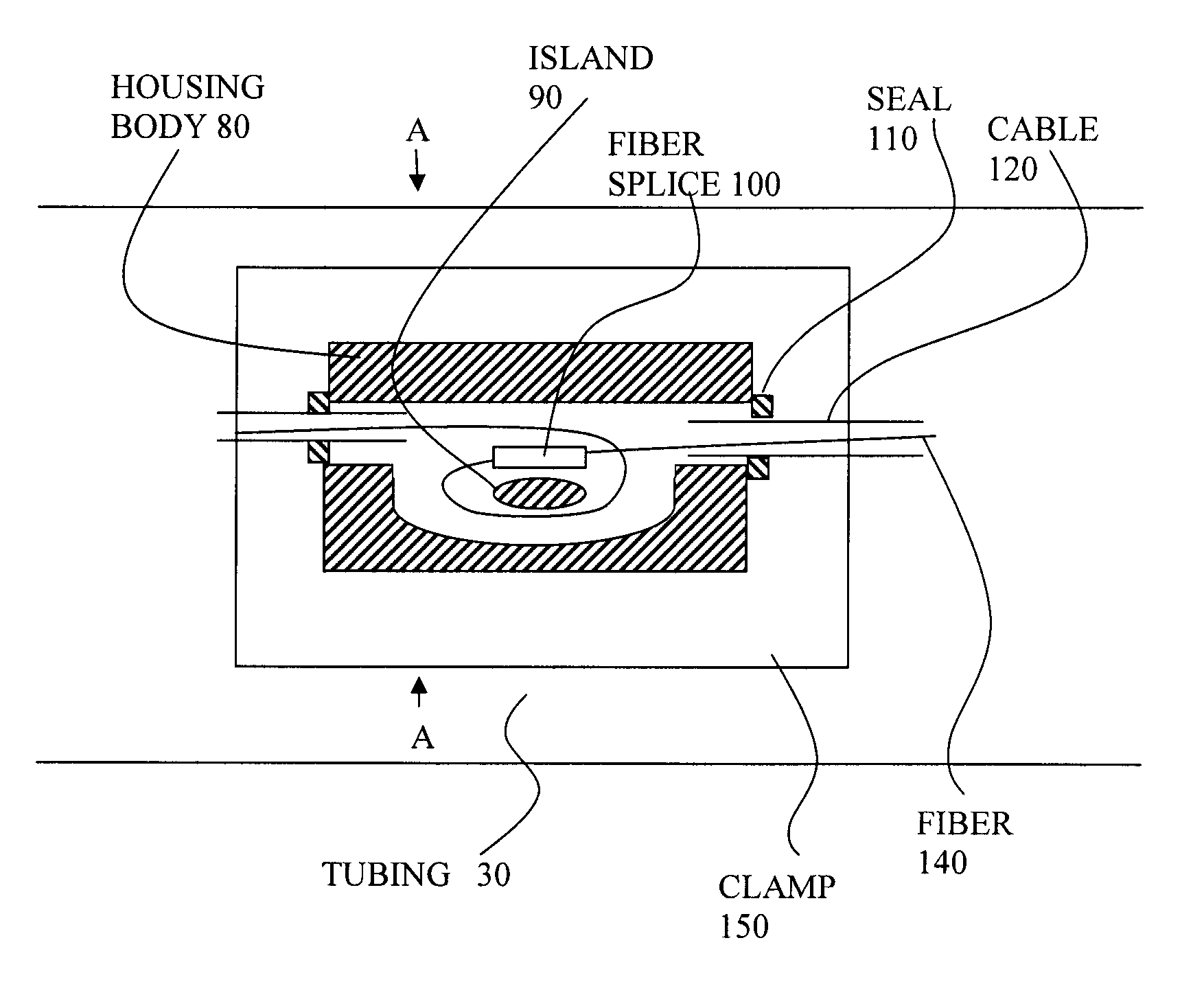
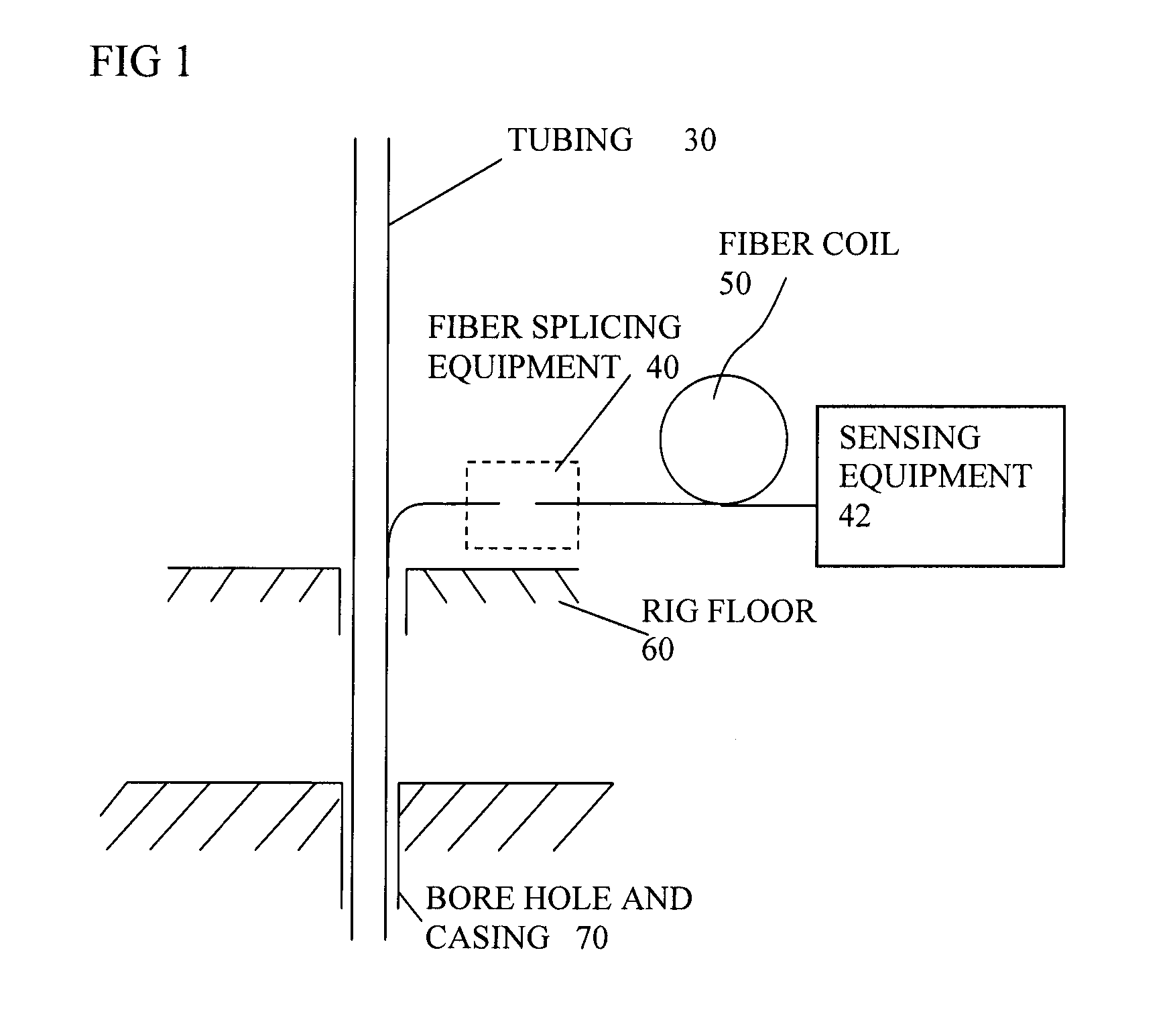
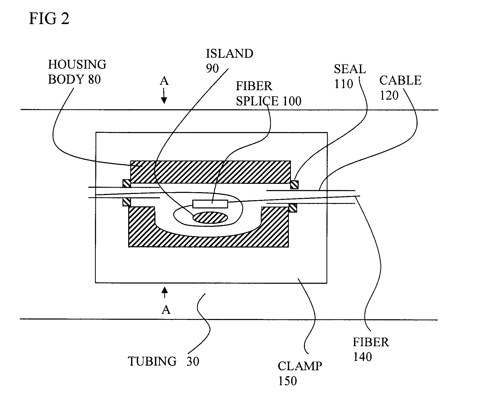
[0030]References to a housing can encompass housings of various sizes or shapes, housings formed of a main body, a lid and a part for attaching, or other parts, or being a one-piece item, with the part for attaching being integral with the main body. The housing can be one-time sealable, or resealable many times. They can be of metal or other materials.
[0031]References to an assembly can encompass parts preassembled, or parts assembled on site.
[0032]References to an arrangement for attaching the housing can encompass any type of fixing, including straps for strapping, clamps of any sort, clamps for clamping the cable to a pipe using well-known collar protectors, as the pipe is placed in a well. Attaching can be by wrapping, by welding, by adhesives, or by physical integration with the tube, or any other way. If the clamp fits around a tube, then the clamp can be arranged to follow the shape of the tube and the main body part need not do so. If the attaching part is...
PUM
| Property | Measurement | Unit |
|---|---|---|
| pressures | aaaaa | aaaaa |
| pressures | aaaaa | aaaaa |
| length | aaaaa | aaaaa |
Abstract
Description
Claims
Application Information