Vibration suppressing device

a technology of vibration suppression and vibration suppression, which is applied in the direction of metal working apparatus, metal-working machine components, manufacturing tools, etc., can solve the problems of reducing the suppression effect of empirical suppression methods based on empirical skill, deteriorating the accuracy of finished surfaces of workpieces, and accelerating tool wear and loss, so as to reduce the impact of time efficiency, the effect of suppressing the most effective suppression of chatter vibrations

Inactive Publication Date: 2011-06-09
OKUMA CORP
View PDF17 Cites 26 Cited by
  • Summary
  • Abstract
  • Description
  • Claims
  • Application Information

AI Technical Summary

Benefits of technology

[0019]According to one or more aspects of the present invention, as mentioned above particularly in the first aspect, an analysis based on a vibration detected by the detector and a computation based on the result of the analysis are performed by the arithmetical unit whenever detection is made, and the result of the analysis and/or the result of the computation are displayed in the display unit in real time. Accordingly, an operator may manipulate the manipulation element while checking the results of analysis and/or computation displayed in the display unit, to change the rotation speed. Thus, the operator can suppress the chatter vibrations more accurately and more swiftly in comparison with the case with the conventional configuration in which the operator should change the rotation speed based on his/her empirical skills or the like.
[0020]Furthermore, the manipulation element is configured to be manipulated to enter a command to change the rotation speed into the rotation speed control unit, as consistent with one or more aspects of the present invention. Thus, the rotation speed of the rotary shaft is changed solely according to the manipulation of the operator, so that the machining operation will be not performed under undesired conditions to the operator. Therefore, the change in the other conditions such as the precision of machining on the surface of a workpiece, the cutting speed of the tool or the like, which had been occurred according to automatical changes of rotation speed in the conventional vibration suppressing device, will not be occurred.
[0021]In this configuration, however, the change in the rotation speed which may be effected through the manipulation element by an operator would possibly change the conditions such as the rigidity of the rotary shaft, and eventually cause chatter vibrations at a different frequency to occur with a good probability as the case may be. Therefore, the configuration in which the operator is allowed to manually change the rotation speed to a stable rotation speed indicated in the display unit would possibly impair the time efficiency in that the operator

Problems solved by technology

In the machining operation of such a machine tool, the so-called “chatter vibrations” generated for one or more reasons such as an excessively increased amount of cut during a cutting operation would cause problems such as deteriorating the accuracy of a finished surface of the workpiece, and accelerating the wear and loss of the tool.
However, the currently prevailing suppressing method based on the operator's empirical skill has limitations on the suppression effects.
Accordingly, even if the vibration suppressing device as d

Method used


Image

  • Vibration suppressing device
  • Vibration suppressing device
  • Vibration suppressing device

Examples


Embodiment Construction

[0039]A vibration suppressing device according to one embodiment of the present invention will be described in detail with reference to the drawings.

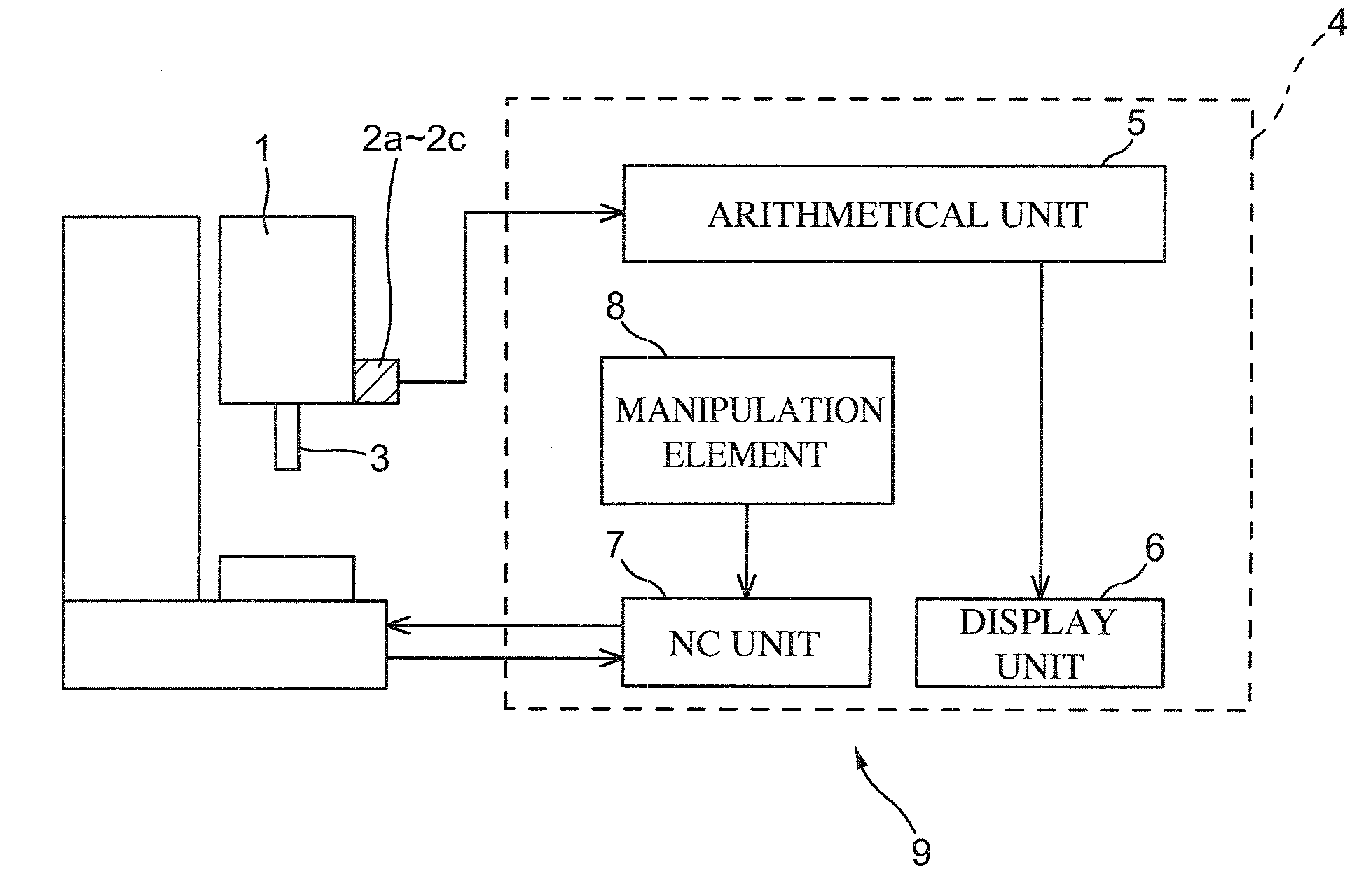
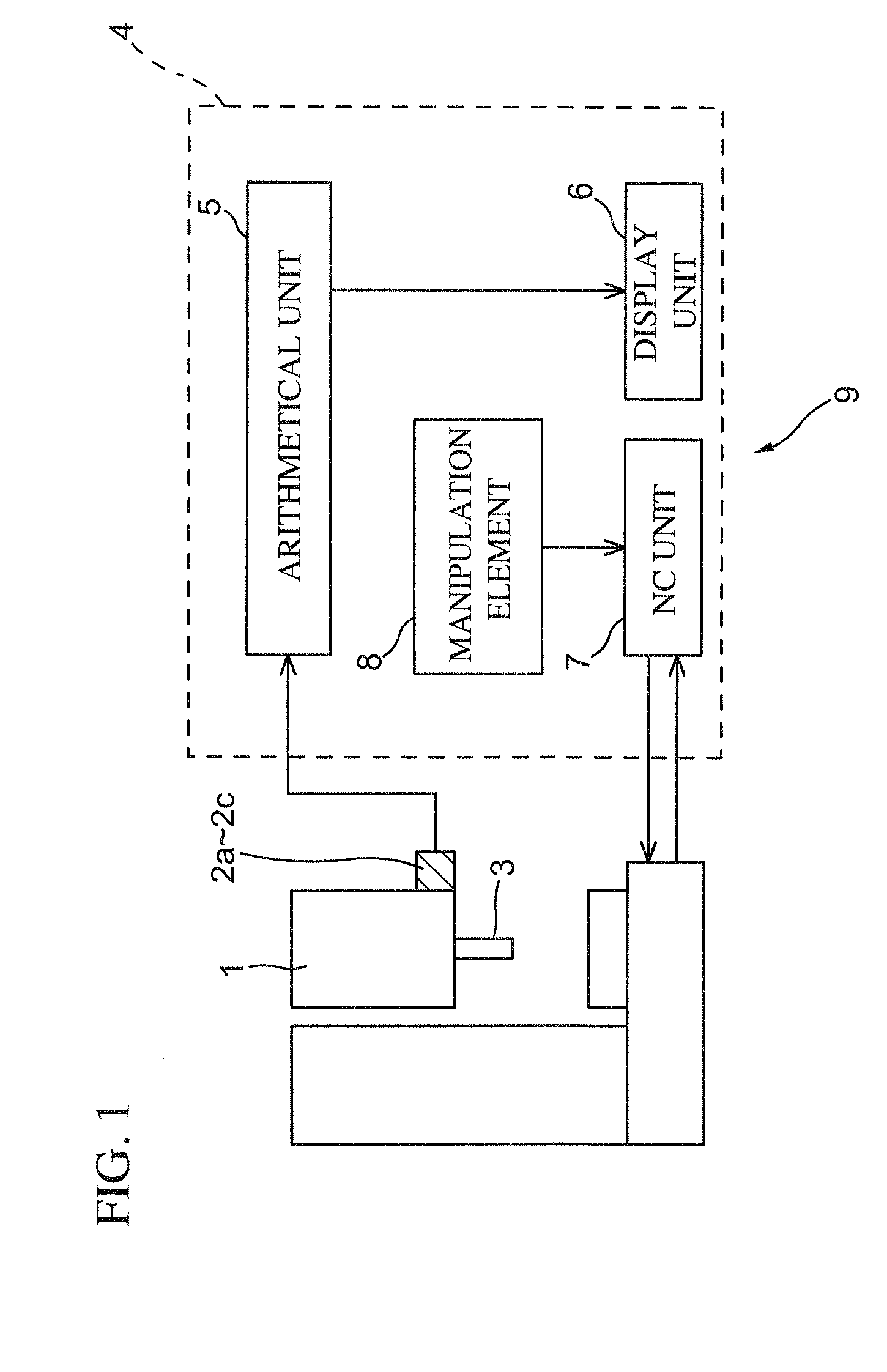
[0040]A vibration suppressing device 9 is a device for suppressing chatter vibrations occurring at a rotary shaft 3 provided in a rotary shaft housing 1 in such a manner that the rotary shaft 3 is rotatable about a C-axis. The vibration suppressing device 9 includes vibration sensors 2a-2c configured to detect vibrational accelerations of the rotary shaft 3 that is rotating, and a controller 4 configured to control over the rotation speed of the rotary shaft 3 to be exercised based on the detection values output from the vibrations sensors 2a-2c.

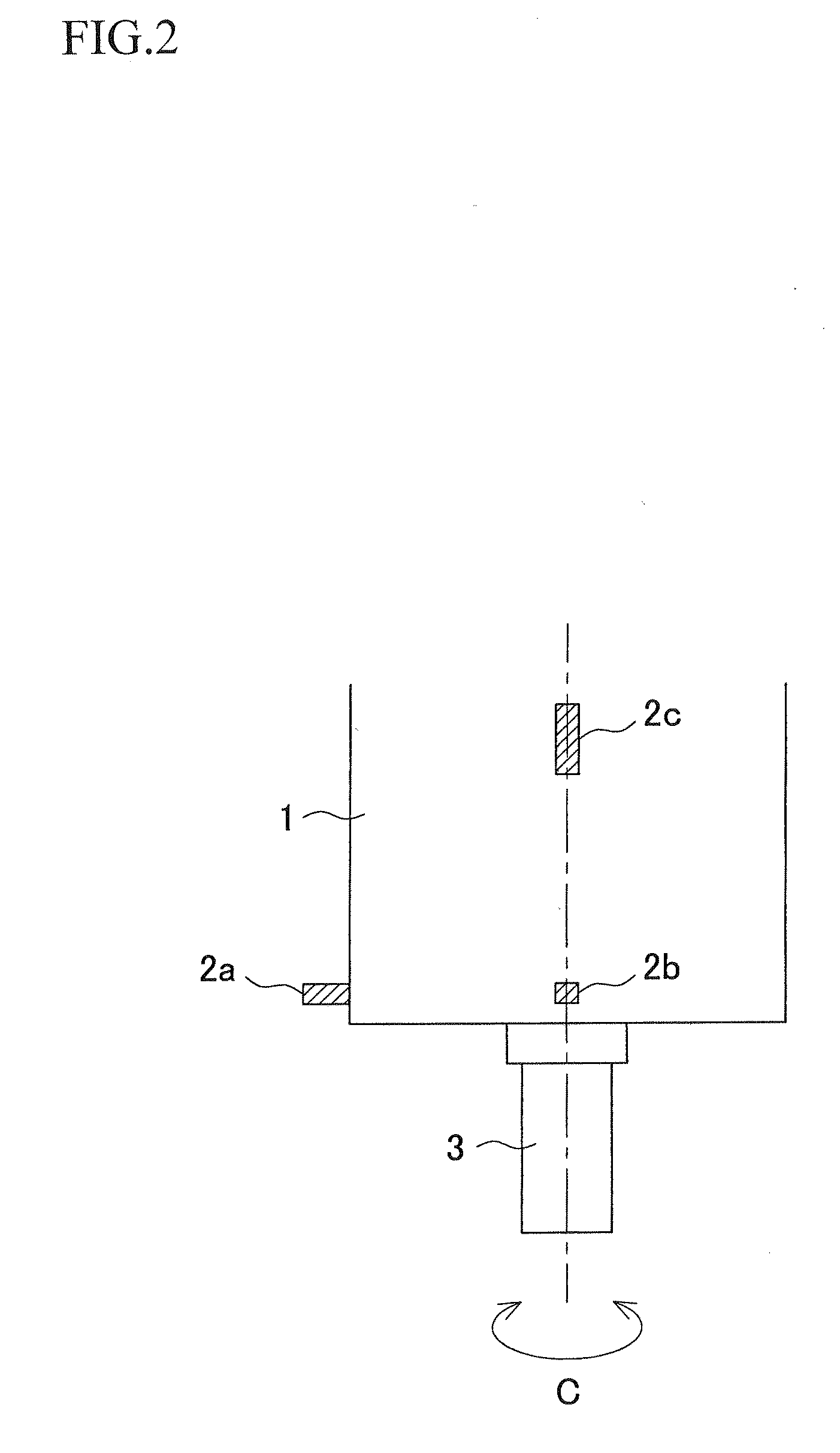
[0041]The vibration sensors 2a-2c are mounted at the rotary shaft housing 1 as shown in FIGS. 2 and 3, and configured such that one vibration sensor detects a vibrational acceleration in a direction perpendicular to directions of vibrational accelerations which the other two vibration sensors d...


PUM

PropertyMeasurementUnit
Speedaaaaaaaaaa

Abstract

In a vibration suppressing device provided in a machine tool having a rotary shaft for use in rotating a tool or a workpiece, for suppressing chatter vibrations generated during rotation of the rotary shaft, an arithmetical unit performs an analysis on a vibration of the rotary shaft detected by a detector (vibrations sensors) whenever the vibration is detected and a computation based on a result of the analysis. An operator, while checking results of the analysis and/or the computation displayed in real time in a display unit, manipulates a manipulation element to enter a command to change a rotation speed of the rotary shaft into a rotation speed control unit (NC unit) which controls the rotation speed according to the command entered by the operator through the manipulation element.

Description

BACKGROUND OF THE INVENTION[0001]This application claims the entire benefit of Japanese Patent Application Number 2009-219454 filed on Sep. 24, 2009, the entirety of which is incorporated by reference.TECHNICAL FIELD[0002]The present invention relates to a vibration suppressing device, provided in a machine tool configured to perform a machining operation on a workpiece with a tool while rotating the tool or the workpiece, for suppressing chatter vibrations generated during the machining operation.BACKGROUND ART[0003]A machine tool in which a tool is supported on a rotary shaft and a machining operation is performed with the spinning tool on a workpiece while the tool and / or the workpiece are being shifted relative to each other is hitherto known in the art. In the machining operation of such a machine tool, the so-called “chatter vibrations” generated for one or more reasons such as an excessively increased amount of cut during a cutting operation would cause problems such as deter...

Claims


Application Information

Patent Timeline
IPC IPC(8): B23Q15/12
CPCB23Q11/0032Y10T409/30084B23Q11/0039
Inventor HAMAGUCHI, AKIHIDEINAGAKI, HIROSHIYOSHINO, KIYOSHIANDO, TOMOHARUUENO, HIROSHI
Owner OKUMA CORP
Why Eureka
Try Eureka