
Thermoplastic Polyolefin Blends

a technology of thermoplastic polyolefin and blend, which is applied in the field of thermoplastic polyolefin blend, can solve the problems of increasing modulus, reducing toughness, and insufficient miscibility of physical blends reducing toughness, and achieving the effect of reducing toughness

Active Publication Date: 2011-06-09
EXXONMOBIL CHEM PAT INC
View PDF53 Cites 33 Cited by
  • Summary
  • Abstract
  • Description
  • Claims
  • Application Information

AI Technical Summary

Benefits of technology

[0016]The present invention provides a polymer blend of a linear ethylene containing polymer, such as a LLDPE, a HDPE or the like, and an in-reactor polymer blend. The in-reactor polymer blend is a mixture of a higher density polyethylene and a lower...

Problems solved by technology

Generally, selecting optimum performance is a matter of trading off one property against another, for example, increasing modulus decreases toughness.
Physical blends have problems of inadequate miscibility.
Reactor blends, also called intimate blends (a composition comprising two or more polymers made in the same reactor or in a series of reactors) are often used to address these issues; however, finding catalyst systems that will operate under the same environments to produce different polymers has been a challenge.
Although the polymer exhibited good tensile properties and elastic recovery, the shear thinning was low.

Method used


Image

  • Thermoplastic Polyolefin Blends
  • Thermoplastic Polyolefin Blends
  • Thermoplastic Polyolefin Blends

Examples


examples 1 to 5

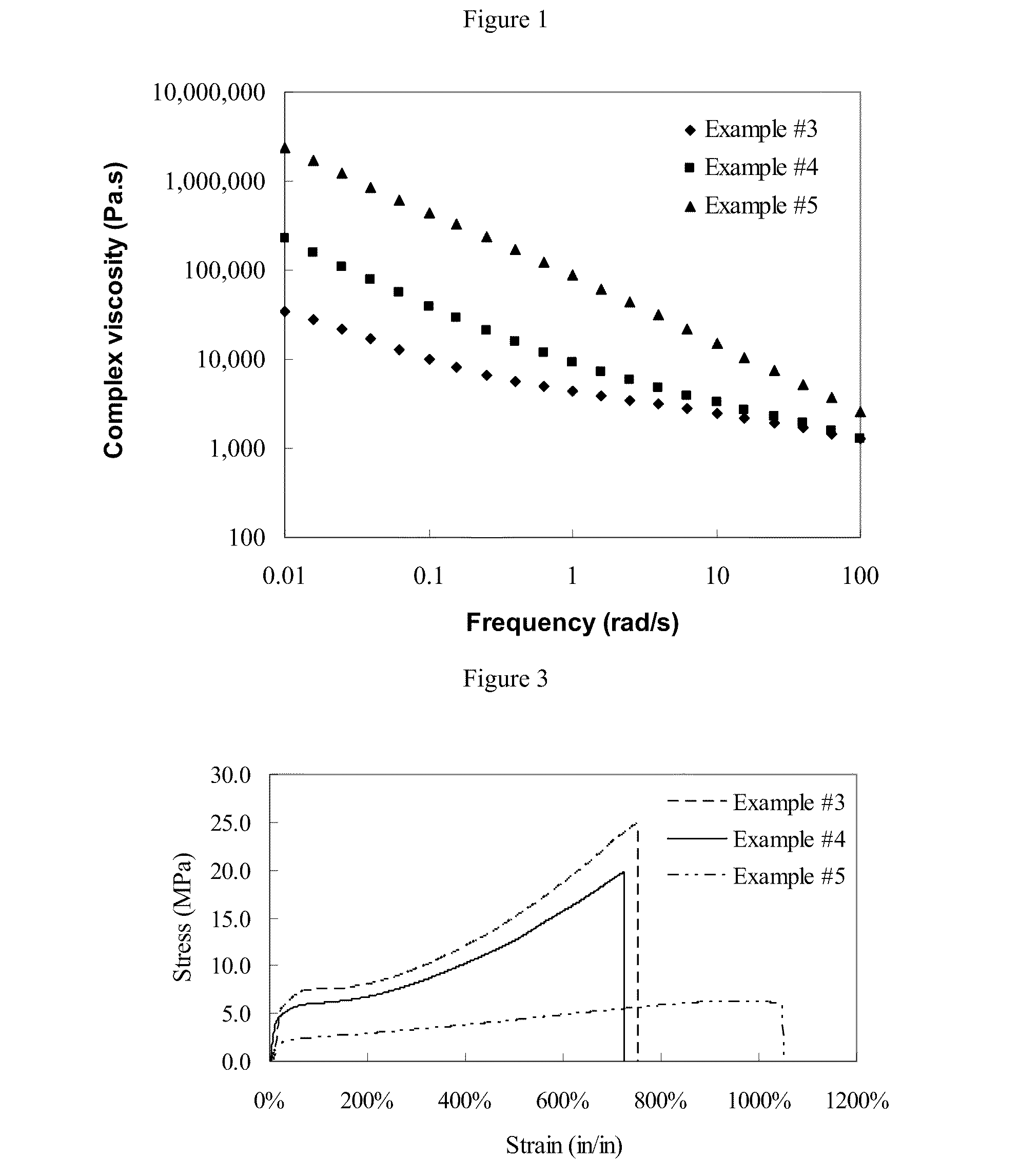
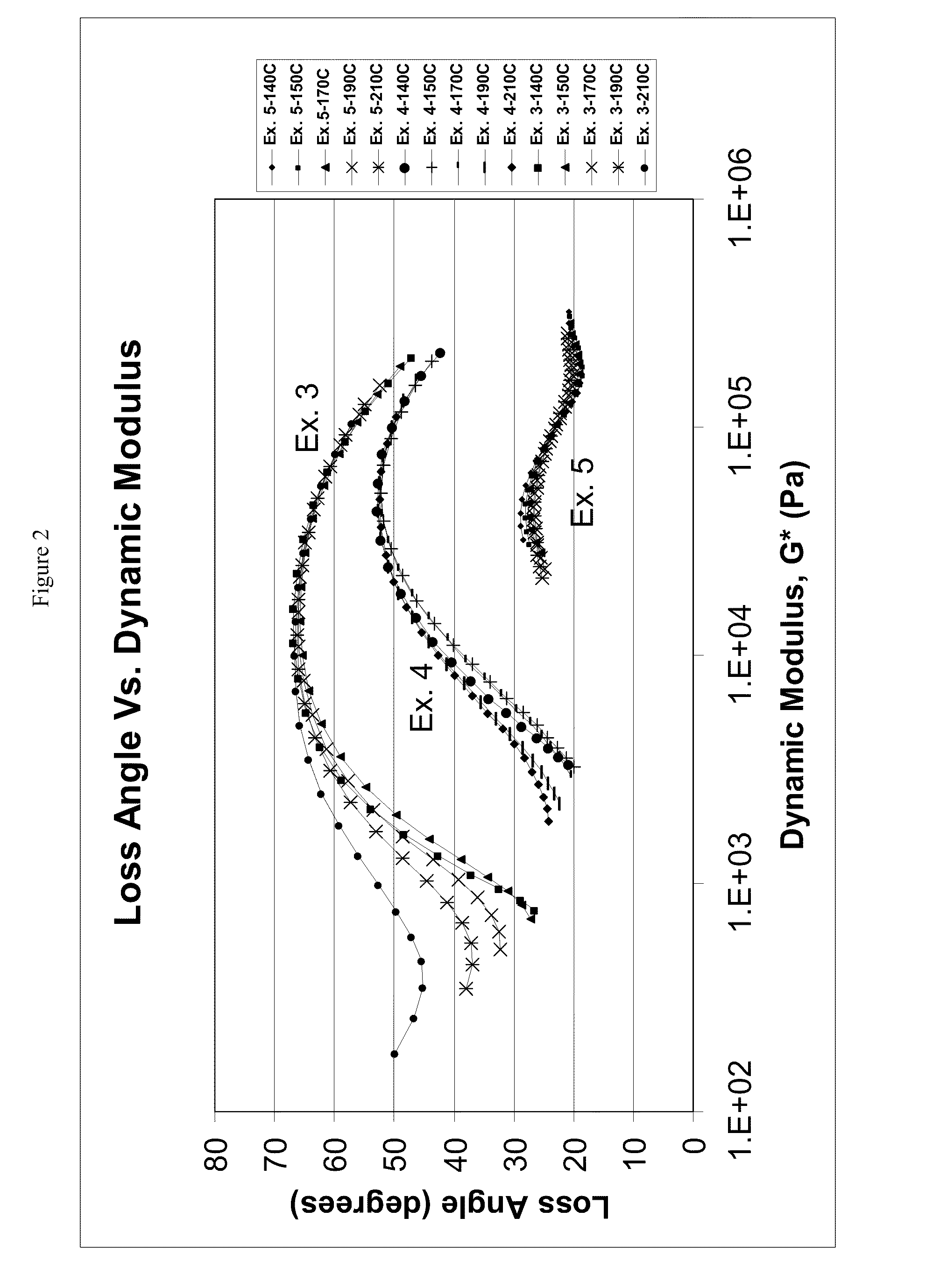
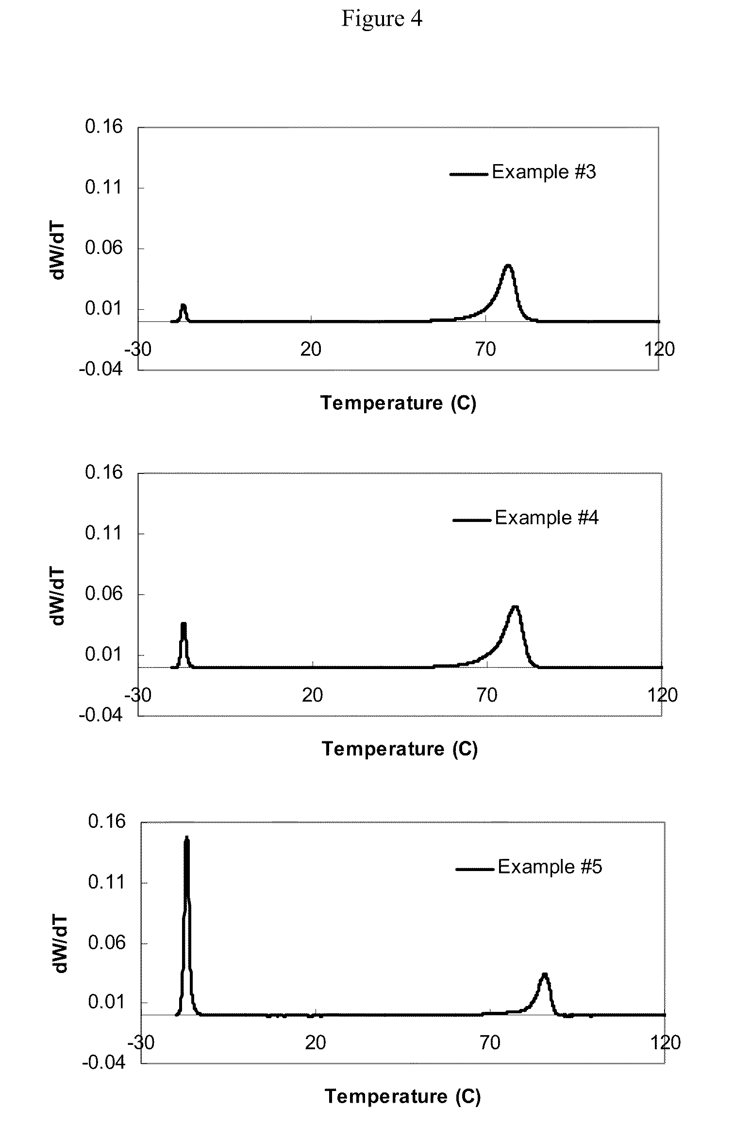
[0280]These examples demonstrate the use of a mixed catalyst polymerization in a single reactor operated in a continuous stirred-tank solution process. The catalysts employed were a biscyclopentadienyl zirconium dimethyl (Catalyst A) to produce higher density polyethylene and 1,1′-bis(4-triethylsilylphenyl)-methylene-(cyclopentadienyl)(2,7-ditert-butyl9-fluorenyl) hafnium dimethyl catalyst (Catalyst B) to produce lower density ethylene / hexene copolymer in the same reactor. The reactor was 1.0-liter stainless steel autoclave reactor equipped with a stirrer, a water-cooling / steam-heating element with a temperature controller, and a pressure controller. Solvents, monomers such as ethylene and hexene were first purified by passing through a three-column purification system. Purification columns were regenerated periodically whenever there was evidence of lower activity of polymerization.

[0281]Catalyst A was preactivated with N,N-dimethylanilinium tetrakis(heptafluoro-2-naphthyl)borate (...

examples 6 to 9

[0295]Examples 6 to 9 were made by following the same procedure used in Examples 1 to 5 except that different types of catalysts were used in Examples 7 and 8. In Example 7, 2,6-diacetylpyridine bis(2,4,6-trimethylphenylimine) iron dichloride (Catalyst C) was used to produce higher density polyethylene and Catalyst B was used for the lower density ethylene / hexene copolymer. 100 mg of 2,6-diacetylpyridine bis(2,4,6-trimethylphenylimine) iron dichloride was first mixed with 8 ml of tri-n-octyl aluminum solution (25 wt %) in 900 ml of toluene for at least 10 minutes, then 160 mg of Activator B was added into the solution to form a catalyst solution. In Example 8, pentamethyl cyclopentadienyl 1,3 dimethyl indenyl hafnium dimethyl (Catalyst D) was used to make higher density polyethylene and Catalyst B was used to produce the lower density ethylene / hexene copolymer. Pentamethyl cyclopentadienyl 1,3 dimethyl indenyl hafnium dimethyl was preactivated with Activator B at a molar ratio of ab...

example 10

[0299]The in-reactor blends produced in Examples 6 to 8 along with the comparative example of Example 9 and the commercial processability improver of LD-PE 200.48 were tested as a modifier (at a concentration of 10 wt %) for Exceed PE 2018E. The blends were prepared using a Brabender mixer (50-g capacity) at a mixing temperature of 200° C. The mixture of Exceed PE 2018 and the in-reactor blend was introduced in the preheated Brabender mixer together with 500 ppm of Irganox 1076 available from Ciba Specialty Chemicals Corporation, Tarrytown, N.Y., 1000 ppm of Irgafos 168 also available from Ciba Specialty Chemicals Corporation, Tarrytown, N.Y., and 800 ppm of Dynamar FX 5920A available from Dyneon LLC, Oakdale, Minn. A rotor speed of 50 rpm was used throughout the run and the system was kept at the temperature desired and stable. Mixing was continued for 10 min once all the blend components were incorporated in the Exceed PE 2018. Finally the blend was discharged from the mixer and a...


PUM

PropertyMeasurementUnit
Temperatureaaaaaaaaaa

Abstract

This invention relates to a blend composition comprising: 1) a linear ethylene containing polymer, such as a LLDPE, a HDPE or the like; and at least 1 weight percent of an in-reactor polymer blend comprising: (a) a first ethylene containing polymer having a density of greater than 0.90 g / cm3 and a Mw of more than 20,000 g / mol; and (b) a second ethylene containing polymer having a density of less than 0.90 g / cm3, wherein the polymer blend has a Tm of at least 90° C. (DSC second melt), a density of less than 0.92 g / cm3, and the densities of the first and second polymers differ by at least 1%. Alternately the in-reactor polymer blend comprises: (a) a first ethylene polymer comprising 90 wt % to 100 wt % ethylene and from 0 wt % to less than 10 wt % comonomer, said first ethylene polymer component having density of greater than 0.920 g / cm3, an Mw of 20,000 g / mol or more; and (b) a second ethylene polymer comprising from 70 wt % to 90 wt % ethylene and 30 wt % to 10 wt % comonomer, said second ethylene polymer having a density of 0.910 g / cm3 or less, wherein the in-reactor polymer blend has one or more of the following characteristics: (a) at least 78 wt % ethylene; (b) a Tm of at least 100° C. over a density ranging from 0.84 to 0.92 g / cm3; (c) a elongation at break of 300% or more; (d) a strain hardening ratio M300 / M100 of at least 1.2; (e) a ratio of complex viscosity at 0.01 rad / s to the complex viscosity at 100 rad / s of at least 30; and (f) a shear thinning index of less than −0.2.

Description

PRIORITY[0001]This application is a continuation in part of U.S. Ser. No. 12 / 638,916, filed Dec. 15, 2009, which is a continuation in part of U.S. Ser. No. 12 / 335,252, filed Dec. 15, 2008.FIELD OF THE INVENTION[0002]This invention relates to the blend compositions comprising a linear ethylene containing polymer and an in-reactor polymer blend comprising two ethylene containing polymers having different comonomer contents.BACKGROUND OF THE INVENTION[0003]Various types of polyethylene are used in the art. Low density polyethylene (“LDPE”) can be prepared at high pressure using free radical initiators, and typically has a density in the range of 0.916-0.940 g / cm3. LDPE is also known as “branched” or “heterogeneously branched” polyethylene because of the relatively high level of long chain branches extending from the main polymer backbone. Polyethylene in the same density range, i.e., 0.916 to 0.940 g / cm3, which is linear and does not contain long chain branching, is also available; thi...

Claims


Application Information

Patent Timeline
IPC IPC(8): C08L23/08C08J3/00
CPCC08L23/04C08L23/06C08L23/08C08L23/0807C08L23/0815C08L2205/02C08L2205/03C08L2314/06C08L2666/02C08L2666/06
Inventor TSE, MUN F.JIANG, PEIJUN
Owner EXXONMOBIL CHEM PAT INC
Learn More