Implantable sensor for measuring physiologic information

a sensor and physiologic technology, applied in the field of implantable sensors for measuring physiologic information, can solve the problems of inconvenient use, inconvenient use, and long medical imaging procedures

Active Publication Date: 2011-06-09
PACESETTER INC
View PDF21 Cites 93 Cited by
  • Summary
  • Abstract
  • Description
  • Claims
  • Application Information

AI Technical Summary

Problems solved by technology

However, such transducers are typically removed after each measurement because the presence of the transducer and associated components within the left ventricle risk causing a stroke.
Accordingly, conventional transducers are generally not implantable within the left ventricle for continuously monitoring heart contractility over time.
However, medical imaging procedures are typically lengthy and expensive, and therefore may not be suitable for monitoring cardiac contractility over time because of the cost and / or inconvenience of the multiple of procedures to the patient.
However, conventional diaphragm-type sensors may need to be hermetically sealed to operate within the human body, and are typically battery-powered.
Conventional diaphragm-type sensors may therefore be bulkier and / or less reliable than is desired for implantation within or adjacent to the heart.
Moreover, the battery may limit the duration for which conventional diaphragm-type sensors may remain operable within the human body without being serviced or replaced.
However, because PZT has a relatively large d33 coefficient, PZT sensors are typically sensitive to hydrostatic pressure and sound waves.
The response caused by such movement may add undesirable noise to the measurement signal of the PZT sensor that represents the motion of the heart, thereby reducing an overall signal clarity of heart contractility information.
The relatively large d33 coefficient of PZT causes PZT to be sensitive to triboelectric charges generated within the PZT sensor by friction between the PZT sensor and surfaces with which the PZT sensor is in contact, thereby further reducing signal clarity of the heart contractility information.
Moreover, because PZT contains lead, PZT may not be biocompatible and therefore not be suitable for implantation within the human body.

Method used


Image

  • Implantable sensor for measuring physiologic information
  • Implantable sensor for measuring physiologic information
  • Implantable sensor for measuring physiologic information

Examples


Embodiment Construction

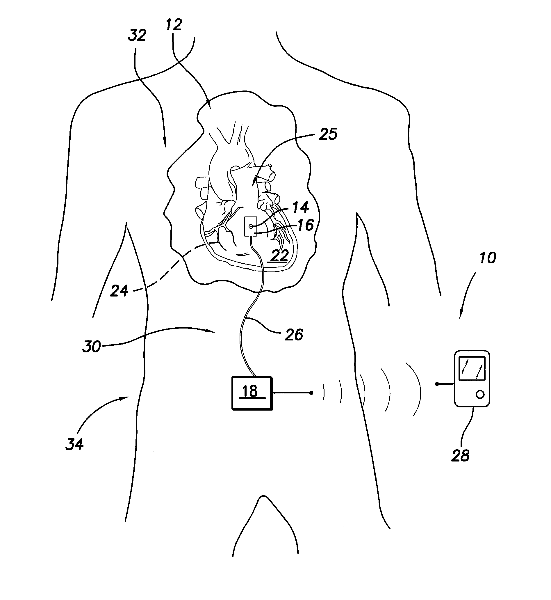
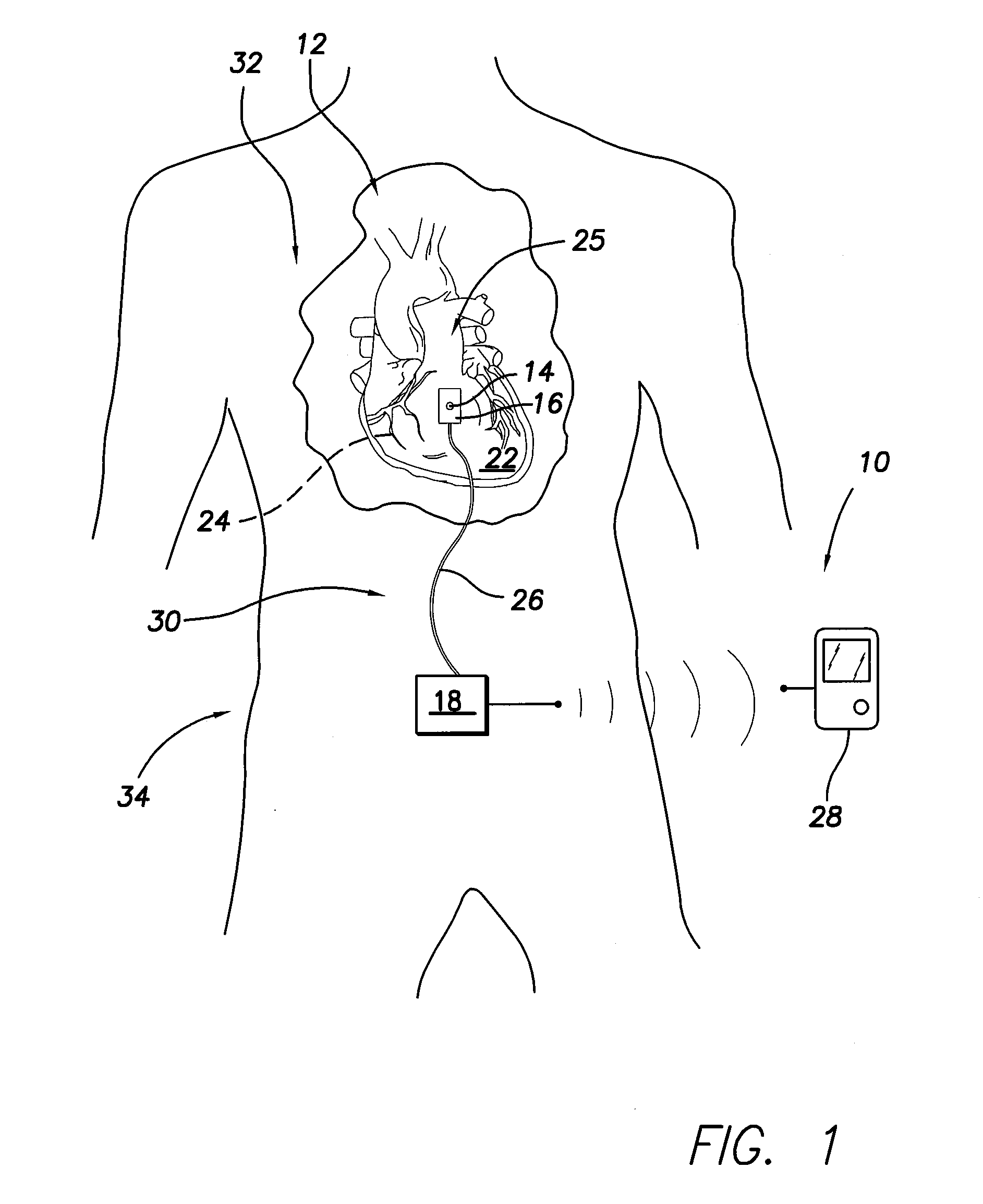
[0024]FIG. 1 illustrates an implantable sensor system 10 formed in accordance with an embodiment of the present invention. The sensor system 10 may be used, for example, for generally monitoring the contractility of a patient's heart 12, e.g., monitoring the diastolic and systolic pump properties of one or both of the ventricles of the heart. The system 10 includes a sensor element 14, an attachment device 16 for positioning the sensor element in direct contact with bodily tissue and / or bodily fluid, and a processing unit 18. The sensor element 14 is fabricated using a “piezopolymer”, which as used herein is intended to mean a polymer having piezoelectric properties. The sensor element 14 may be fabricated from any suitable piezopolymer(s) that enables the sensor element 14 to function as described herein, such as, but not limited to, polyvinylidene fluoride (PVDF).

[0025]As will be described in more detail below, the sensor element 14 bends in response to motion of the bodily tissue...


PUM


Abstract

An implantable sensor is provided that includes a piezopolymer sensor element including a body having a plurality of layers of a piezopolymer, and an attachment device configured to hold the piezopolymer sensor element in direct contact with at least one of a bodily fluid and bodily tissue such that the piezopolymer sensor element is configured to bend in response to motion of the at least one of bodily fluid and bodily tissue. A pair of electrodes is attached to the piezopolymer sensor element and the electrodes are configured to collect an electrical charge that is generated within the piezopolymer sensor element due to the bending of the piezopolymer sensor element.

Description

CROSS REFERENCE TO RELATED APPLICATIONS[0001]This application is a continuation of copending U.S. patent application Ser. No. 11 / 750,226, filed May 17, 2007, titled “Implantable Sensor for Measuring Physiologic Information.”FIELD OF THE INVENTION[0002]Embodiments of the present invention pertain generally to methods and systems for measuring cardiac-related physiologic information utilizing an implantable sensor, for example, for the treatment and / or diagnosis of congestive heart failure.BACKGROUND OF THE INVENTION[0003]In the United States, it is estimated that approximately five million people have congestive heart failure (CHF). During treatment of some CHF patients, the contractility of the heart may be assessed for diagnosis and / or treatment purposes. In addition to being useful for generally monitoring the progression of a patient's cardiac disease, the heart's contractility may be monitored over time to monitor the patient's response to therapy and make any appropriate change...

Claims


Application Information

Patent Timeline
Patent Type & Authority Applications(United States)
IPC IPC(8): A61B5/02
CPCA61B5/0295A61B5/1107A61B2562/0261A61B5/6869A61B5/688A61B5/6833
Inventor YANG, MICHAELHOU, WENBO
Owner PACESETTER INC
Why Eureka
Try Eureka