Carbon dioxide refrigerant vapor compression system

a technology of refrigerant vapor and carbon dioxide, which is applied in the direction of refrigeration safety arrangement, refrigeration components, lighting and heating apparatus, etc., can solve the problem of complex control of system refrigerant charg

Active Publication Date: 2011-06-16
CARRIER CORP
View PDF18 Cites 57 Cited by
  • Summary
  • Abstract
  • Description
  • Claims
  • Application Information

AI Technical Summary

Benefits of technology

[0007]In an aspect of the invention, a carbon dioxide refrigerant vapor compression system includes a refrigerant circuit having a refrigerant compression device, a refrigerant heat rejection heat exchanger for passing refrigerant received from the compression device at a high pressure in heat exchange relationship with a cooling medium, a refrigerant heating heat exchanger for passing refrigerant at a low pressure refrigerant in heat exchange relationship with a heating medium, and an expansion device disposed in the refrigerant circuit downstream of the refrigerant cooling heat exchanger and upstream of the refrigerant heating heat exchanger. A flash tank receiver is disposed in the refrigerant circuit downstream of the refrigerant heat rejection heat exchanger and upstream of the expansion device. Additionally, the refrigerant vapor compression system includes a compressor unload circuit having a refrigerant line establishing refrigerant flow communication between an intermediate pressure stage of the compression device and the refrigerant circuit at a location downstream of the refrigerant heat absorption heat exchanger and upstream of a suction inlet to the compression device, and a unload circuit flow control device disposed in the unload circuit refrigerant line. A controller is provided in operative association with the expansion device and the unload circuit flow control valve. The controller operates in response to at least one system operating parameter sensed by at least one sensor to selectively position the unload flow control device to maintain the refrigerant vapor compression system operating at a discharge pressure below a preselected upper limit pressure. In an embodiment, the sensed operating parameter may, for example, be the refrigerant discharge pressure or the ref

Problems solved by technology

In a transcritical refrigerant vapor compression system, however, controlling the system refrigerant charge is more complex because the compressor high side refrigerant leaving the gas cooler is above the refrigerant's crit

Method used


Image

  • Carbon dioxide refrigerant vapor compression system
  • Carbon dioxide refrigerant vapor compression system

Examples


Embodiment Construction

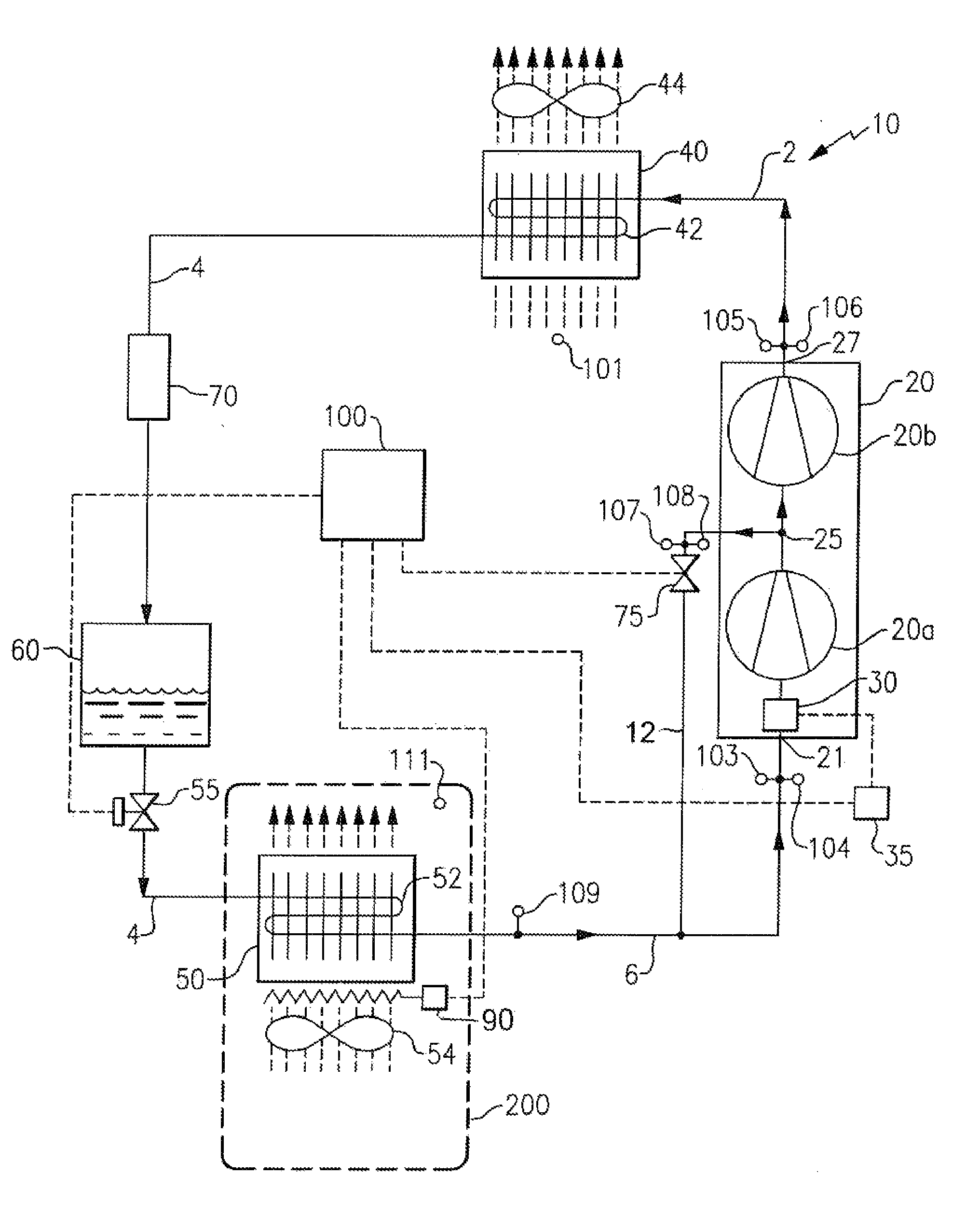
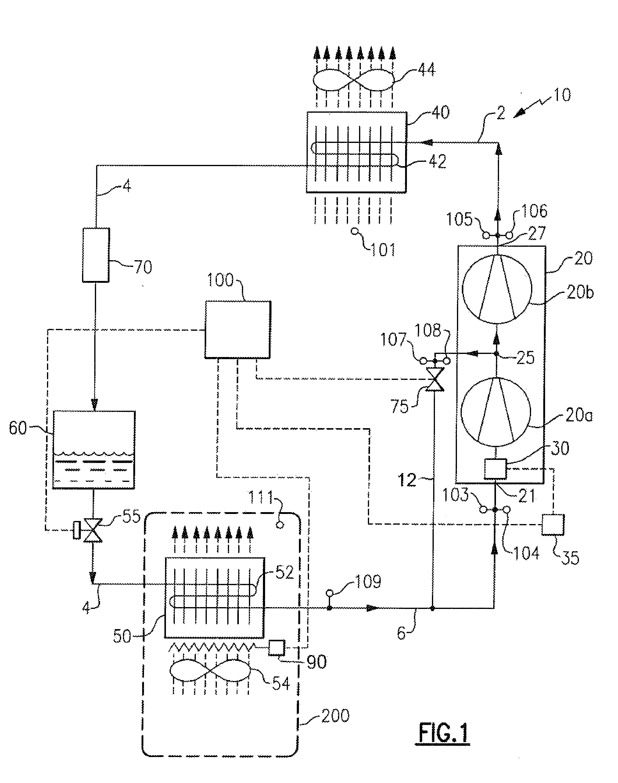
[0011]Referring now to FIG. 1, the refrigerant vapor compression system 10 includes a compression device 20 driven by a motor 30 operatively associated therewith, a refrigerant heat rejecting heat exchanger 40, a refrigerant heat absorbing heat exchanger 50, also referred to herein as an evaporator, connected in a closed loop refrigerant circuit in series refrigerant flow arrangement by various refrigerant lines 2, 4 and 6. Additionally, the refrigerant vapor compression system 10 includes a flash tank receiver 60 disposed in refrigerant line 4 of the refrigerant circuit downstream with respect to refrigerant flow of the refrigerant heat rejecting heat exchanger 40 and upstream with respect to refrigerant flow of the evaporator 50, and an evaporator expansion device 55, operatively associated with the evaporator 50, disposed in refrigerant line 4 downstream with respect to refrigerant flow of the flash tank receiver 60 and upstream with respect to refrigerant flow of the evaporator ...


PUM


Abstract

A carbon dioxide refrigerant vapor compression system and method of operating that system are provided. The refrigerant vapor compression system includes a compression device, a flash tank receiver disposed in the refrigerant circuit intermediate a refrigerant heat rejection heat exchanger and a refrigerant heat absorption heat exchanger, and a compressor unload circuit including a refrigerant line establishing refrigerant flow communication between an intermediate pressure stage of the compression device and the refrigerant circuit at a location downstream of the refrigerant heat absorption heat exchanger and upstream of a suction inlet to the compression device, and a unload circuit flow control device disposed in said unload circuit refrigerant line. In response to at least one system operating parameter sensed by at least one sensor, the controller selectively positions the unload flow control device to maintain the refrigerant vapor compression system operating below a preselected high pressure limit.

Description

FIELD OF THE INVENTION[0001]This invention relates generally to refrigerant vapor compression systems and, more particularly, to a refrigerant vapor compression system using carbon dioxide refrigerant.BACKGROUND OF THE INVENTION[0002]Refrigerant vapor compression systems are well known in the art and commonly used for conditioning air to be supplied to a climate controlled comfort zone within a residence, office building, hospital, school, restaurant or other facility. Refrigerant vapor compression systems are also commonly used in transport refrigeration systems for refrigerating air supplied to a temperature controlled cargo space of a truck, trailer, container or the like for transporting perishable items. Traditionally, most of these refrigerant vapor compression systems operate at subcritical refrigerant pressures and typically include a compressor, a condenser, and an evaporator, and expansion device, commonly an expansion valve, disposed upstream, with respect to refrigerant ...

Claims


Application Information

Patent Timeline
IPC IPC(8): F25B1/00F25B41/04
CPCF25B2309/061F25B49/02F25B2400/16F25B2600/0253F25B2600/0261F25B2600/2501F25B2600/2513F25B2700/193F25B2700/1931F25B2700/1933F25B2700/2115F25B2700/21151F25B2700/21152F25B2700/21161F25B2700/21173F25B2700/21175Y02B30/741F25B1/10F25B9/008F25B2400/01Y02B30/70
Inventor CHEN, YU H.DURAISAMY, SURESHLIU, LUCY YISCARCELLA, JASONASPROVSKI, ZVONKOLAMENDOLA, KURSTENMITRA, BISWAJIT
Owner CARRIER CORP
Why Eureka
Try Eureka