Fixed Moment Arm Combustion Apparatus

a combustion apparatus and fixed moment technology, applied in mechanical equipment, machines/engines, gearing, etc., can solve the problems of unresolved apparatus need, high fuel consumption for rated power output, waste of energy,

Inactive Publication Date: 2011-06-16
CNG DESIGN
View PDF9 Cites 12 Cited by
  • Summary
  • Abstract
  • Description
  • Claims
  • Application Information

AI Technical Summary

Problems solved by technology

The displacement of the connecting rod allows only a component of the combustion force to be transmitted to the crank assembly and hence results in wastage of energy and high fuel consumption for a rated power output.
Hen

Method used


Image

  • Fixed Moment Arm Combustion Apparatus
  • Fixed Moment Arm Combustion Apparatus
  • Fixed Moment Arm Combustion Apparatus

Examples


Embodiment Construction

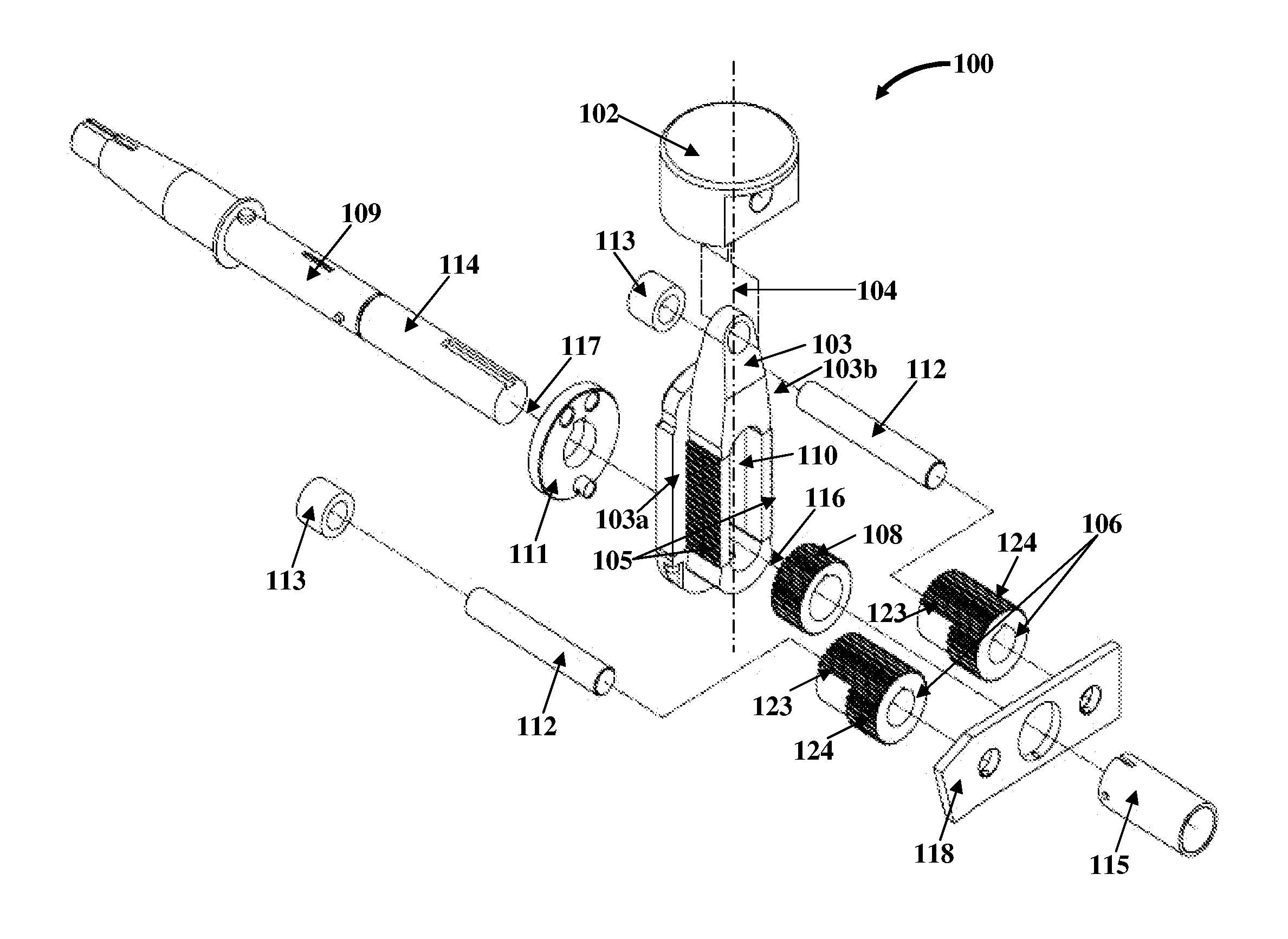
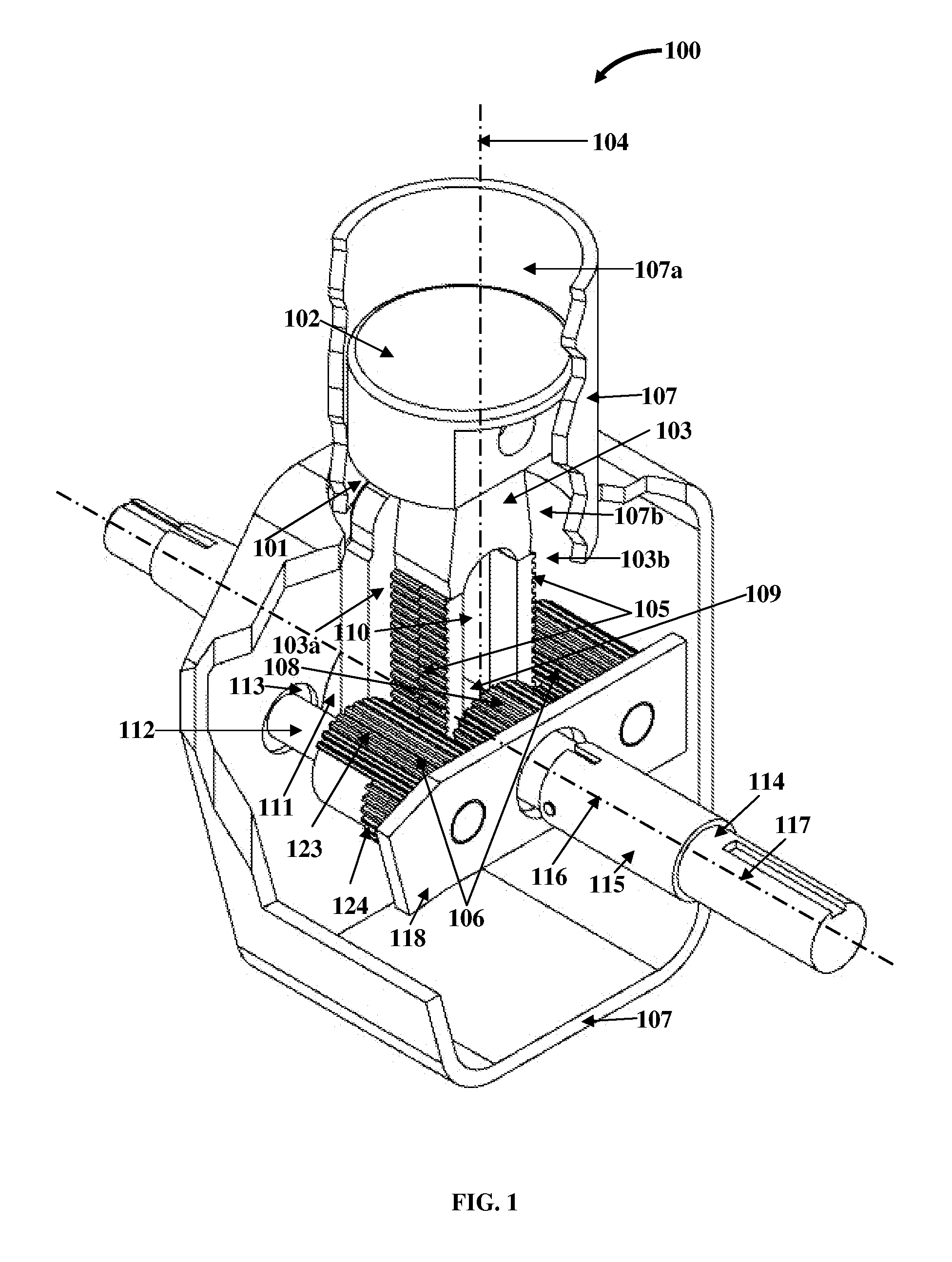
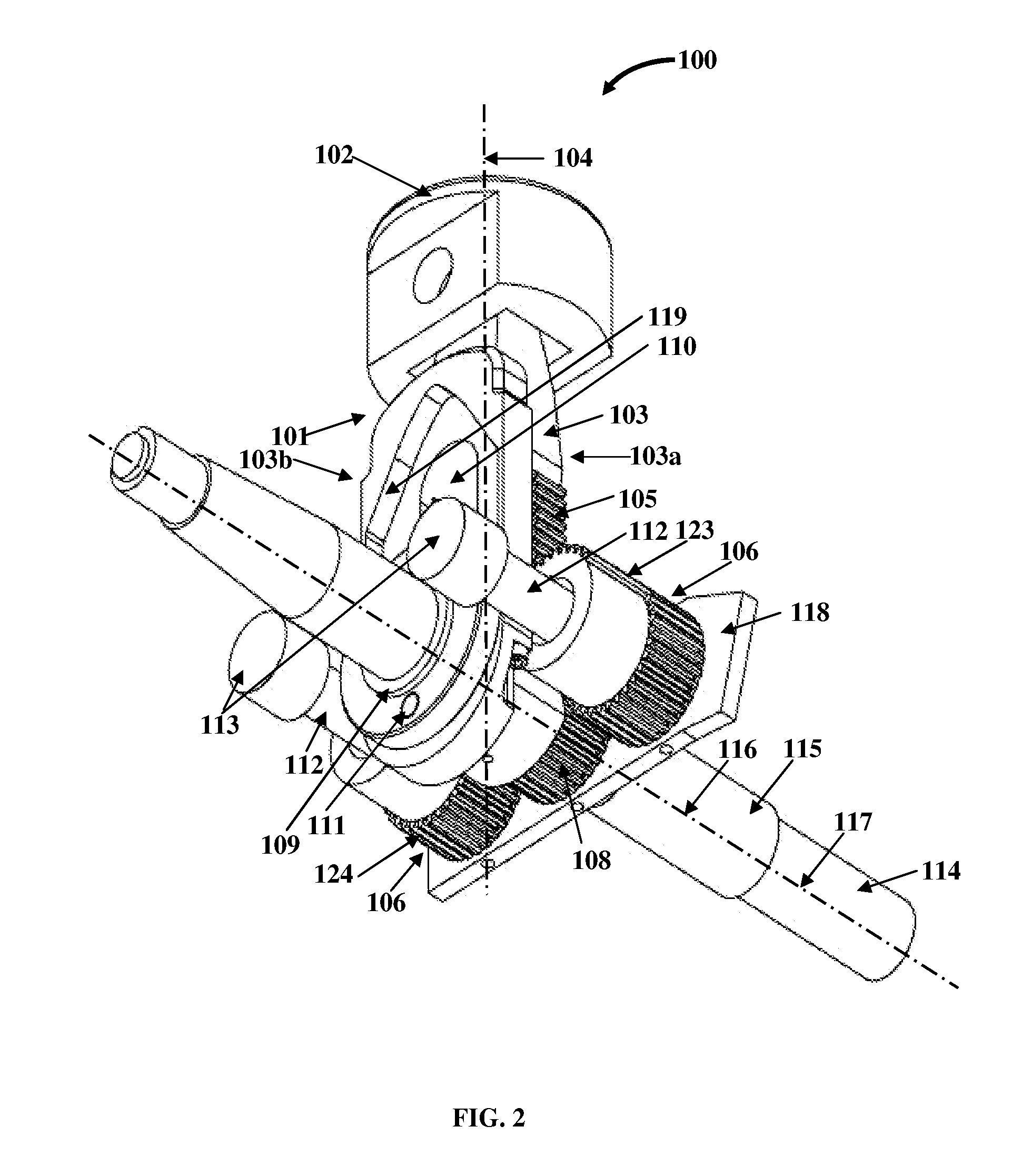
[0039]FIG. 1 exemplarily illustrates a front perspective view of an apparatus 100 for converting linear reciprocal motion to rotary motion. The apparatus 100 disclosed herein comprises at least one reciprocating assembly 101, gear racks 105, and gearing elements 106. The reciprocating assembly 101 comprises a reciprocating component 102 and a reciprocating rod 103 capable of linear reciprocal motion in unison. The reciprocating component 102 is rigidly attached to the reciprocating rod 103 along a vertical axis 104 of the reciprocating rod 103. The reciprocating component 102 is supported by a housing 107. The reciprocating component 102 is a piston and is herein referred to as a “piston”102. The reciprocating rod 103 is slidably connected to an idler gear 108 via a guide pin 109 as exemplarily illustrated in FIG. 3. The gear racks 105 disposed on opposing sides 103a and 103b of the reciprocating rod 103 transmit motion to the gearing elements 106. The reciprocating rod 103 comprise...


PUM


Abstract

An apparatus for converting linear reciprocal motion to rotary motion is provided. The apparatus comprises a reciprocating assembly comprising a reciprocating component and a reciprocating rod. The reciprocating component is rigidly attached to the reciprocating rod and is supported by a housing. The reciprocating rod is slidably connected to an idler gear via a guide pin. Multiple gear racks are disposed on the reciprocating rod for transmitting motion to one or more gearing elements. The gearing elements are disposed on opposing sides of the reciprocating rod and are in alternate mesh with the gear racks to transmit the motion to the idler gear. Each of the gearing elements and each of the gear racks together define a fixed moment arm. The gearing elements mesh with the idler gear rigidly mounted on a power shaft to convert linear reciprocal motion of the reciprocating assembly to rotary motion of the power shaft.

Description

CROSS REFERENCE TO RELATED APPLICATIONS[0001]This application claims the benefit of provisional patent application No. 61 / 285,544 titled “Fixed Moment Arm Combustion Engine”, filed on Dec. 11, 2009 in the United States Patent and Trademark Office.[0002]The specification of the above referenced application is incorporated herein by reference in its entirety.BACKGROUND[0003]Conventional reciprocating engines consist of a cylinder body and a piston with a connecting rod and a crank assembly. During operation of a conventional reciprocating engine, the connecting rod and crank assembly convert linear reciprocal motion to rotary motion. A mixture of fuel and air is ignited in the cylinder body and a combustion force is produced as a result of the ignition of the mixture of fuel and air. The piston executes linear reciprocal motion. The connecting rod is displaced, horizontally and vertically, along a vertical plane when the piston executes the linear reciprocal motion. This displacement ...

Claims


Application Information

Patent Timeline
IPC IPC(8): F16H19/04
CPCF01B9/047Y10T74/18112F16H19/043F16C7/02
Inventor CARR, WILLIAM JAMES
Owner CNG DESIGN
Why Eureka
Try Eureka