
Fixed Moment Arm Internal Gear Drive Apparatus

Inactive Publication Date: 2012-08-16
CNG DESIGN
View PDF8 Cites 1 Cited by
  • Summary
  • Abstract
  • Description
  • Claims
  • Application Information

AI Technical Summary

Benefits of technology

[0006]The fixed moment arm internal gear drive apparatus disclosed herein addresses the above stated need for converting linear reciprocal motion to rotary motion by eliminating and replacing a crank assembly with a fixed moment arm. This is achieved by means of a fixed moment arm orientation between an internal gear rack of a reciprocating rod and a segmented gear that is in alternate mesh with the internal gear rack of the reciprocating rod, in which the combustion force is always perpendicular to the surface on which the combustion force is transmitted. Therefore, the apparatus disclosed herein, with the fixed moment arm orientation between the internal gear rack of the reciprocating rod and the segmented gear, possesses an inherent advantage over conventional reciprocating engines. The reciprocating rod of the apparatus disclosed herein transmits all or most part of the combustion force into driving the segmented gear. Furthermore, the apparatus disclosed herein has a larger effective moment arm compared to a conventional reciprocating engine. In operation, the apparatus disclosed herein inherently eliminates the presence of angularity while transmitting the combustion force from the reciprocating rod to the segmented gear, and also transmits the combustion force perpendicularly from the reciprocating rod to the segmented gear at all times. The apparatus disclosed herein recovers a part of the wasted energy and uses the recovered energy to drive a power shaft.
[0010]The transfer plates are coaxially disposed on a centric axis of the segmented gear and rigidly connected to the power shaft. The transfer plates are rigidly connected and timed to the segmented gear. Each of the transfer plates comprises one or more profiled grooves for controlling transition of the reciprocating rod by contacting the reciprocating rod, when the reciprocating component is at the top dead center and the bottom dead center within the engine housing to enable smooth frictionless movement of the reciprocating rod. The segmented gear transmits the rotary motion to the transfer plates for rotating the transfer plates.
[0011]The transfer plates receive power from the segmented gear. The transfer plates, rigidly connected and timed to the segmented gear, assist and facilitate smooth alternate meshing of the segmented gear with the internal gear racks of the reciprocating rod. The transfer plates further comprise one or more balancing reliefs defined along a circumference of the transfer plates for stabilizing the transfer plates.

Problems solved by technology

The displacement of the connecting rod allows only a component of the combustion force to be transmitted to the crank assembly and hence results in wastage of energy and high fuel consumption for a rated power output.
Furthermore, as the connecting rod reciprocates there is a tendency for the connecting rod to lose a part of its energy to frictional losses in every stroke that the connecting rod undertakes.
Prolonged use of the connecting rod without the use of external fixtures results in wear and tear of the material of the connecting rod.
Moreover, in a geared system, the inability to control the connecting rod causes misalignment and locking of mating gears which affects the working of the engine.
Hence, there is a long felt but unresolved need for a fixed moment arm internal gear drive apparatus that converts linear reciprocal motion to rotary motion, recovers a part of the wasted energy, and uses the recovered energy to drive a power shaft.

Method used


Image

  • Fixed Moment Arm Internal Gear Drive Apparatus
  • Fixed Moment Arm Internal Gear Drive Apparatus
  • Fixed Moment Arm Internal Gear Drive Apparatus

Examples


Embodiment Construction

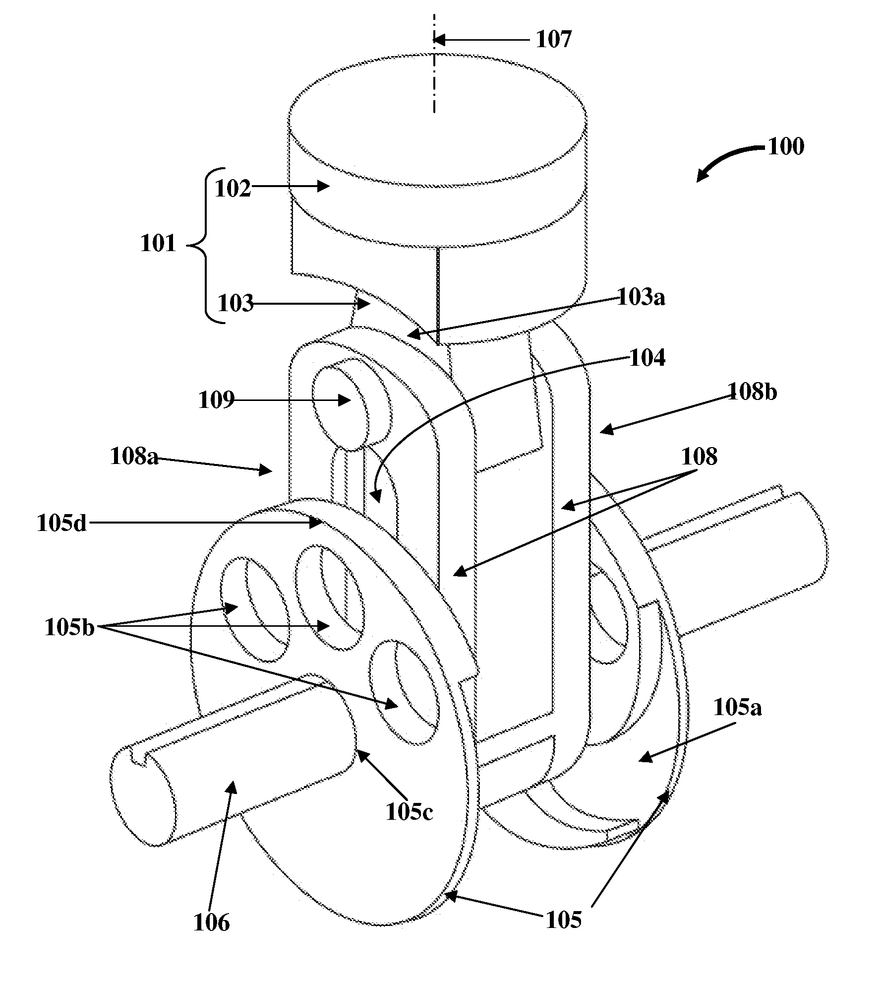
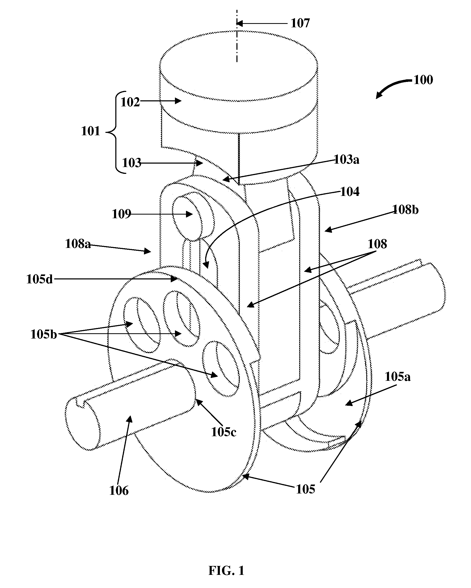
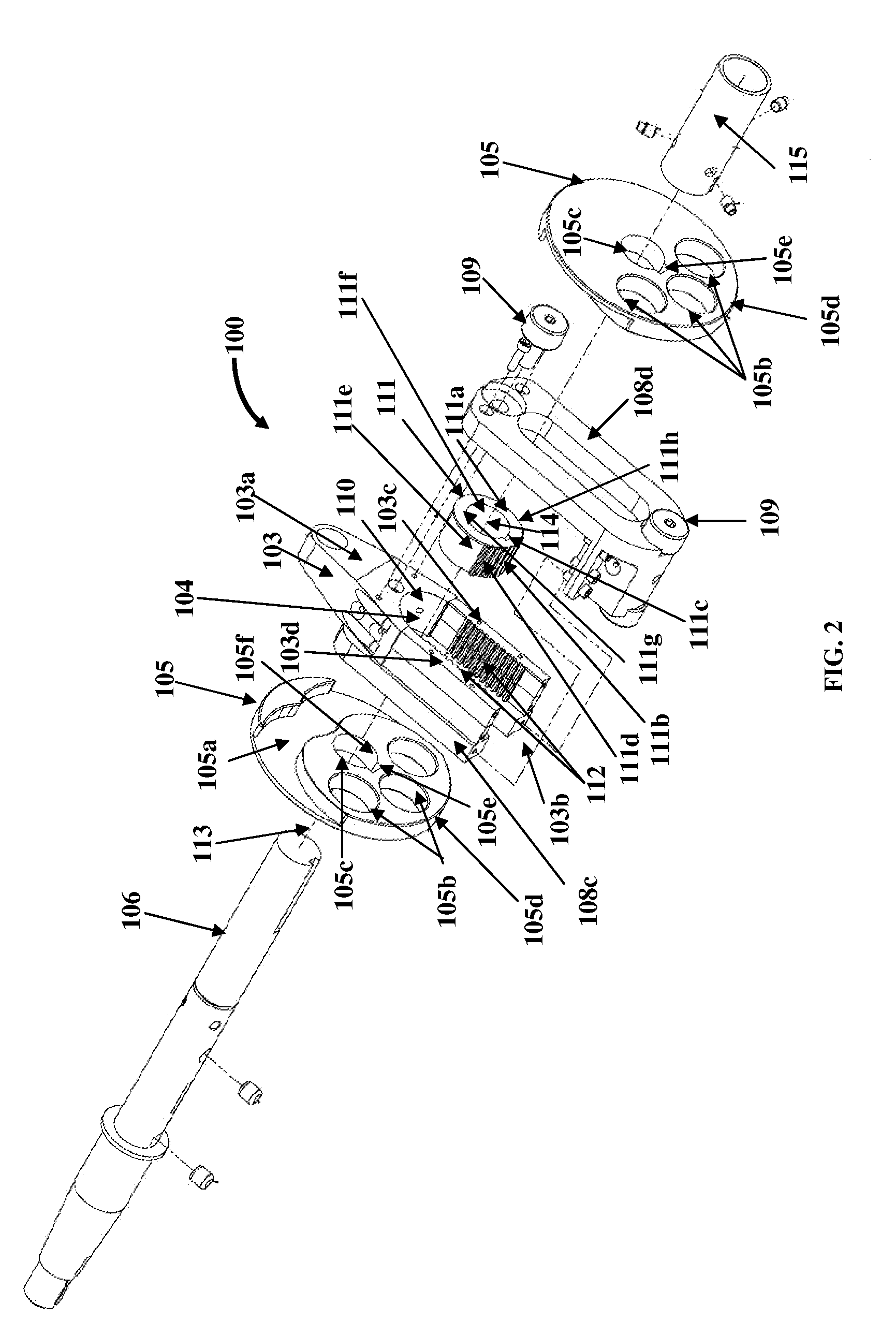
[0032]FIG. 1 exemplarily illustrates a perspective view of a fixed moment arm internal gear drive apparatus 100 for converting linear reciprocal motion to rotary motion. The fixed moment arm internal gear drive apparatus 100 disclosed herein comprises at least one reciprocating assembly 101, multiple internal gear racks 112, a segmented gear 111, and one or more transfer plates 105 as exemplarily illustrated in FIG. 2 and FIG. 7. The reciprocating assembly 101 comprises a reciprocating component 102 and a reciprocating rod 103 capable of linear reciprocal motion in unison. The reciprocating component 102 is a piston 102. The reciprocating component 102 is supported in an engine housing 118 as exemplarily illustrated in FIG. 7. The reciprocating component 102 is rigidly attached to the reciprocating rod 103 along a vertical axis 107 of the reciprocating rod 103. The reciprocating rod 103 is enclosed and supported by a rod housing 108. The reciprocating rod 103 comprises an elongated ...


PUM


Abstract

An apparatus for converting linear reciprocal motion to rotary motion, comprising a reciprocating component and a reciprocating rod capable of linear reciprocal motion in unison, internal gear racks, a segmented gear, and transfer plates is provided. The internal gear racks are disposed on opposing internal sides of the reciprocating rod for inducing rotary motion in the segmented gear by linear reciprocal motion of the reciprocating rod. The segmented gear, disposed within a space defined between the opposing internal sides of the reciprocating rod and rigidly connected to a power shaft, alternately meshes with the internal gear racks to transmit rotary motion to the power shaft. The transfer plates, coaxially disposed on the segmented gear's centric axis, comprise profiled grooves for controlling transition of the reciprocating rod by contacting the reciprocating rod, when the reciprocating component is at a top dead center and a bottom dead center within an engine housing.

Description

BACKGROUND[0001]Conventional reciprocating engines consist of a cylinder body and a piston with a connecting rod and a crank assembly. During operation of a conventional reciprocating engine, the connecting rod and the crank assembly convert linear reciprocal motion to rotary motion. A mixture of fuel and air is ignited in the cylinder body and a combustion force is produced as a result of the ignition of the mixture of fuel and air. The piston executes linear reciprocal motion in response to the combustion force. The connecting rod is displaced along a vertical plane when the piston executes the linear reciprocal motion. This displacement of the connecting rod angularly displaces the combustion force while transmitting the combustion force to the crank assembly. The angular displacement of the combustion force varies with respect to the position of the piston in the cylinder body. Thus, a variable moment arm exists and subsequently a constantly varying component of the combustion f...

Claims


Application Information

Patent Timeline
IPC IPC(8): F16H25/08
CPCF02B75/32Y10T74/18056F16H19/043F01B9/047
Inventor CARR, WILLIAM JAMES
Owner CNG DESIGN
Learn More