Premix gas burner

a gas burner and pre-mix technology, applied in the direction of gaseous fuel burners, fuel supply regulation, combustion process, etc., can solve the problems of high head loss, low efficiency of fans, and no effect, and achieve the effect of easy and inexpensive production

Active Publication Date: 2011-06-16
GAS POINT
View PDF7 Cites 131 Cited by
  • Summary
  • Abstract
  • Description
  • Claims
  • Application Information

AI Technical Summary

Benefits of technology

[0049]Consequently, the aim of the present invention is to provide a premix burner which will be fre

Problems solved by technology

However, given that this variation is very small, it is altogether of no effect for the purposes of the present treatment.
However, premix burners of the types described with reference to FIGS. 1 and 2 present the following disadvantages:a modulation range that varies from 100% to 20% (ratio 1:5) of the nominal thermal power; andhigh losses of head at the maximum thermal power.
This type of boiler must have, however, the capacity to supply continuously (i.e., without any turning-off of the burner) energy to a markedly differentiated extent, i.e., a very high extent for the production of water for sanitary purposes and a very limited extent for the production of heat for the heating system.
; above 6000 r.p.m. the efficiency of th

Method used


Image

  • Premix gas burner
  • Premix gas burner
  • Premix gas burner

Examples


first embodiment

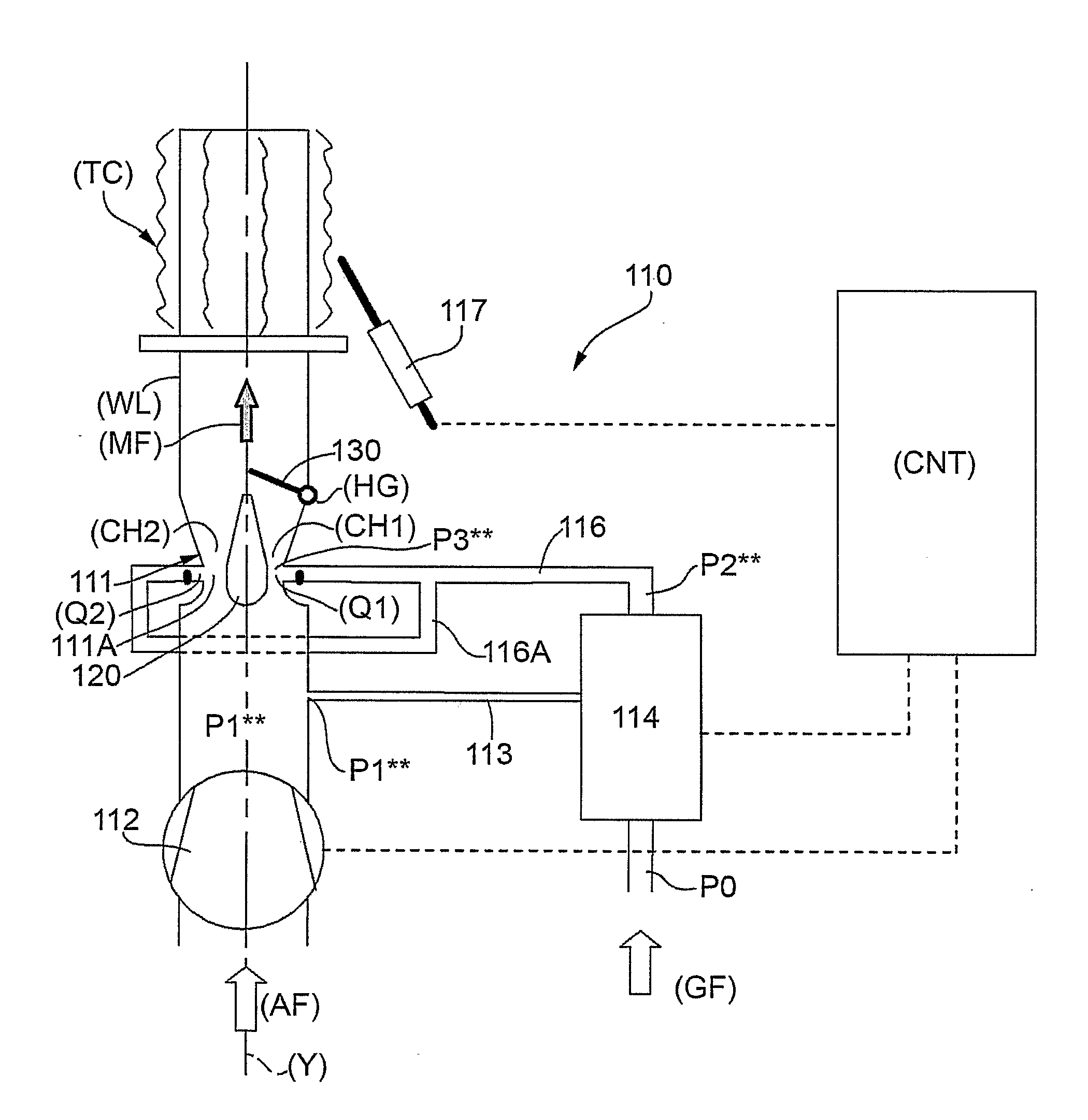
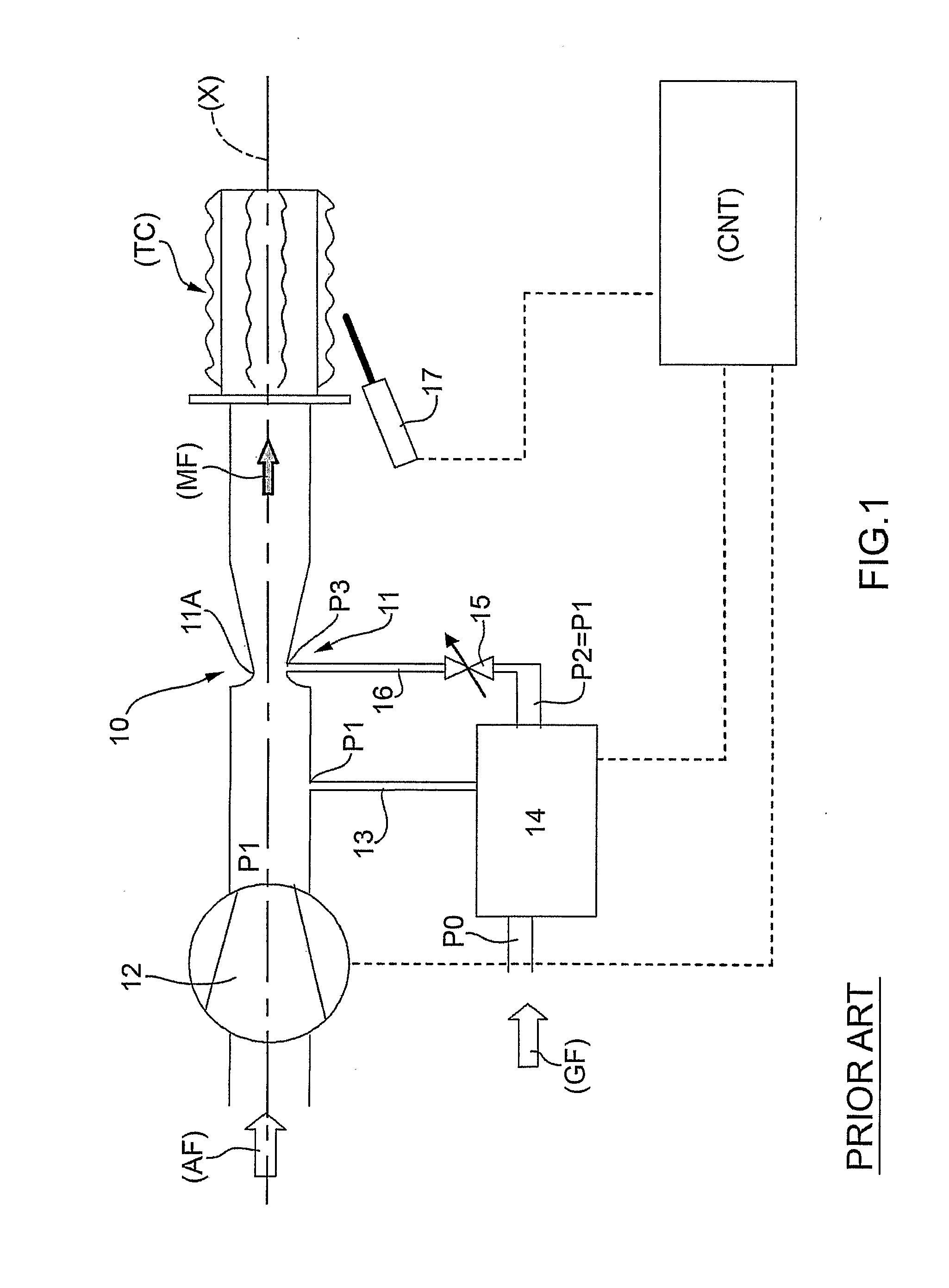
[0055]The diagram of FIG. 1 must be considered as the starting point for the present invention illustrated in FIG. 3.

[0056]Consequently, in the diagram of FIG. 3 the elements that are identical or similar to the ones already described have been numbered by adding the number 100 to the numbering used in FIG. 1.

[0057]For reasons of concision, the various elements comprised in the burner 110 with vertical axis (Y) will not be described again in detail.

[0058]A characterizing element of the embodiment illustrated in FIG. 3 is constituted by the fact that the Venturi-tube air / gas mixer 111 is divided into two channels (CH1), (CH2) by a baffle element 120.

[0059]The dimensions of the minimum sections of the channels (CH1, CH2) for mixing of the fluids are the same as one another so as to generate, given the same air flow passing through, the same pressure difference.

[0060]As an alternative to what has been seen in the previous point, the dimensions of the minimum sections of the channels (C...

second embodiment

[0084]Represented in FIG. 4 is a premix burner with horizontal axis (X).

[0085]In addition, the premix burner can present an axis inclined by any desirable amount with respect to a horizontal (X) or vertical (Y) axis.

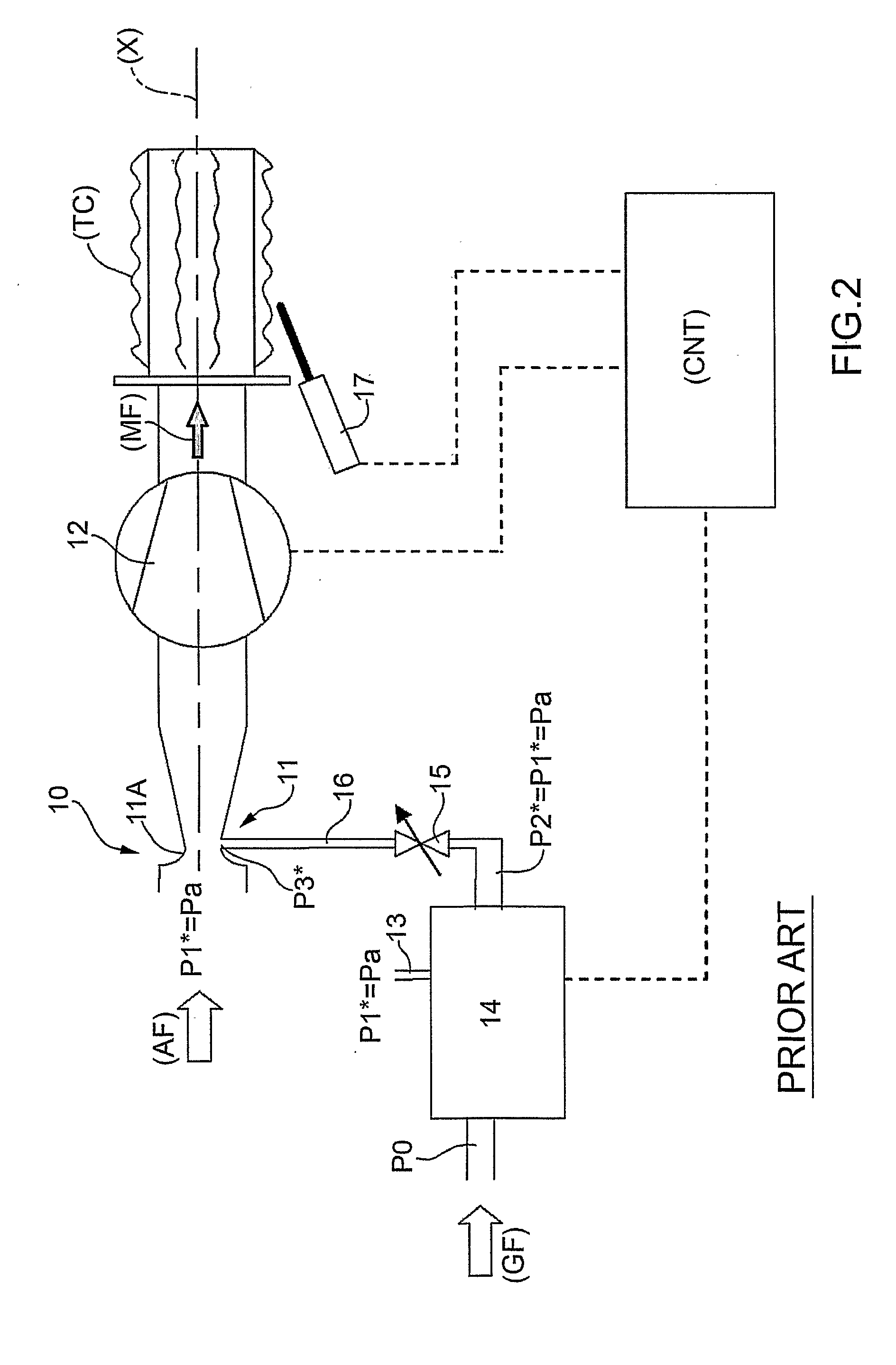
[0086]The diagram of FIG. 2 (with fan set downstream of the area of mixing) is to be considered the starting point for the second embodiment of the present invention illustrated in FIG. 4.

[0087]Consequently, in the diagram of FIG. 4 the elements that are identical or similar to ones already described have been numbered by adding the number 200 to the numbering used in FIG. 2.

[0088]For reasons of concision we shall not describe again in detail the various elements comprised in the burner 210 with horizontal axis (X).

[0089]A characterizing element of the embodiment illustrated in FIG. 4 is represented by the fact that the Venturi-tube air / gas mixer 211 (with a localized-pressure-loss device 211A) is divided into two channels (CH1), (CH2) by a baffle element 220. The open / c...

third embodiment

[0093]FIG. 5 illustrates a third embodiment in which an air / gas mixer 311 (with a localized-pressure-loss device 311A) envisages a respective diaphragm 340, 350 in a position corresponding to each channel (CH1), (CH2). In addition, each diaphragm 340, 350, in turn, has a respective central hole 340A, 350A that enables flow of the air pushed by the fan 312.

[0094]The two perforated diaphragms 340, 350 illustrated are also two areas of localized pressure loss for the air flow, which enable mixing with the gas coming from the conduit 316.

[0095]Once again, the channel (CH1) is provided with an open / close element 330 that closes the channel (CH1) itself with the modalities seen above.

[0096]The same conclusions are reached by replacing the hinged open / close elements 130, 230, 330 with the floating open / close elements (not illustrated in the attached figures).

[0097]In addition, the table appearing below presents a practical example, which sets in comparison the results obtained with the bur...


PUM


Abstract

An air/gas premix burner, comprising:
    • a fan for sending the air/gas mixture to a combustion head;
    • a gas valve for regulating admission of the combustible gas;
    • an air/gas mixer, which comprises a device for localized loss of pressure; and
    • a combustion head.
The premix burner is characterized in that the air/gas mixer comprises at least two channels for mixing the air with the gas; in addition, a channel is provided with an open/close element designed to regulate the flow rate of the mixture.

Description

TECHNICAL FIELD[0001]The present invention relates to a premix gas burner with total premixing of gas / air.BACKGROUND ART[0002]As is known, premix burners with total air / gas premixing are today widely used for producing thermal energy in gas boilers.[0003]The use of these burners is rapidly spreading replacing traditional atmospheric burners in so far as, as compared with the latter, they enable:[A] lower emissions of pollutant substances (nitrogen and carbon oxides);[B] high heat-exchange efficiency at all thermal-power regimes and in particular at the minimum thermal power; and[C] high modulation range between the maximum and the minimum thermal power of the burner.[0004]Air / gas premix burners are today prevalently obtained using the following essential components:[0005]a fan for delivery of the air / gas mixture to a combustion head;[0006]a gas valve actuated pneumatically equipped with a flow regulator;[0007]an air / gas mixing system constituted by a Venturi tube or by a diaphragm p...

Claims


Application Information

Patent Timeline
IPC IPC(8): F23D14/64F23N1/02
CPCF23D14/60F23D14/64F23N5/242F23D2900/14642F23N1/022F23D2900/00003
Inventor ZATTI, CLAUDIORASTELLI, RAFFAELLOLOVASCIO, NICOLA
Owner GAS POINT
Why Eureka
Try Eureka