
Speed control systems and methods for internal combustion engines

a technology of internal combustion engine and control system, which is applied in the direction of electric control, speed sensing governor, machine/engine, etc., can solve the problems of not being able to provide as rapid a response to control signals, traditional engine control system, and not being able to control the torque output of the engine as accurately as desired

Inactive Publication Date: 2011-06-16
GM GLOBAL TECH OPERATIONS LLC
View PDF29 Cites 51 Cited by
  • Summary
  • Abstract
  • Description
  • Claims
  • Application Information

AI Technical Summary

Benefits of technology

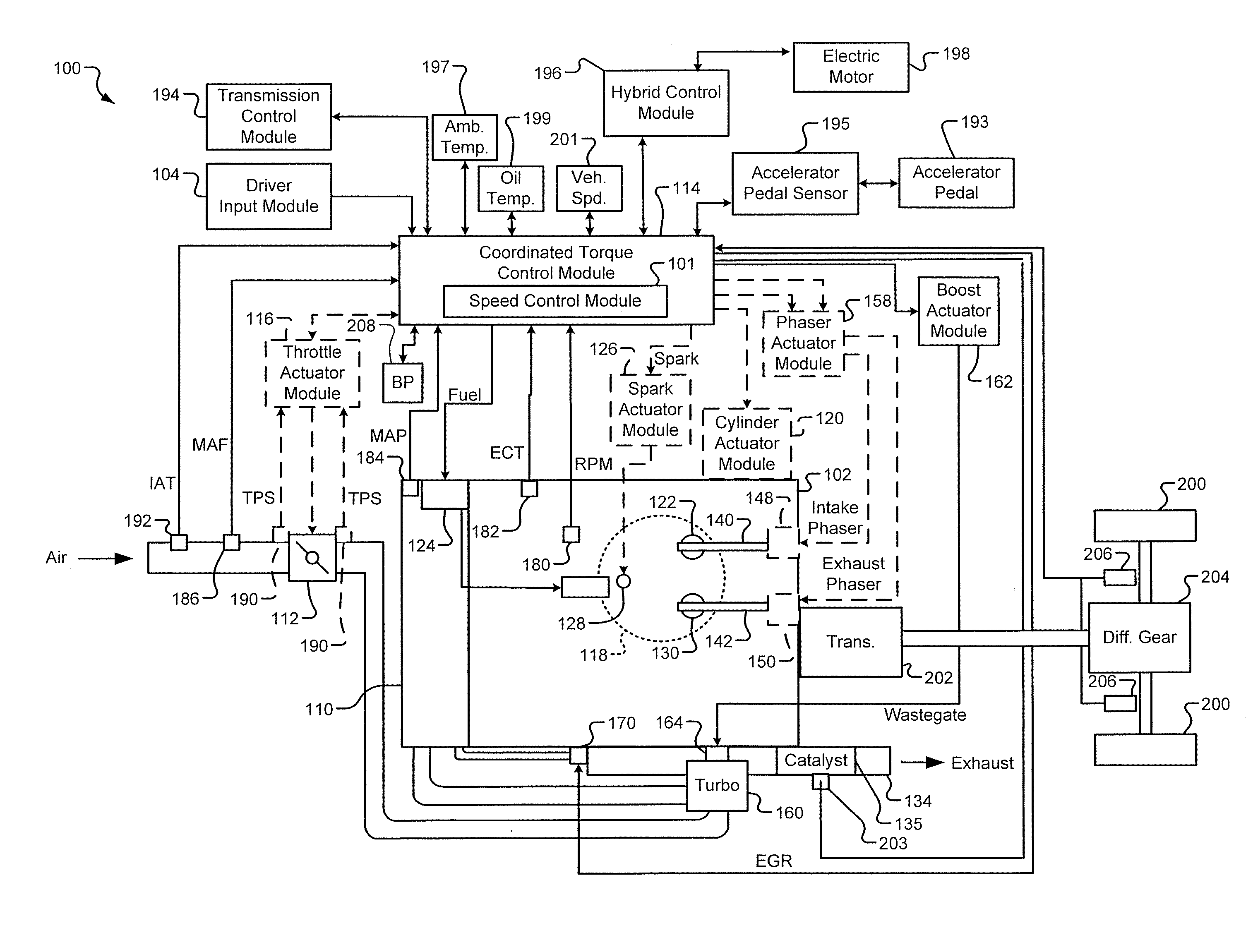
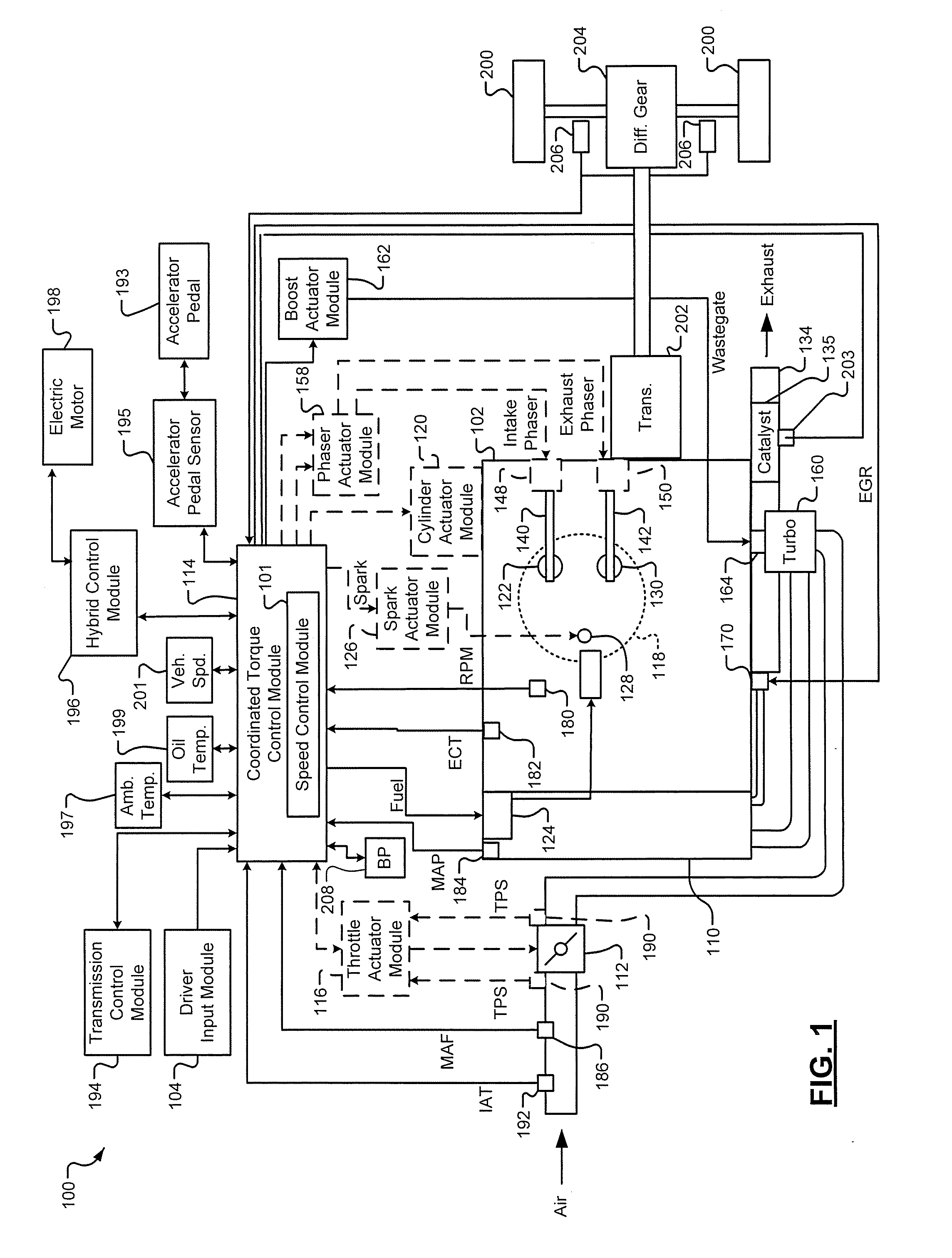
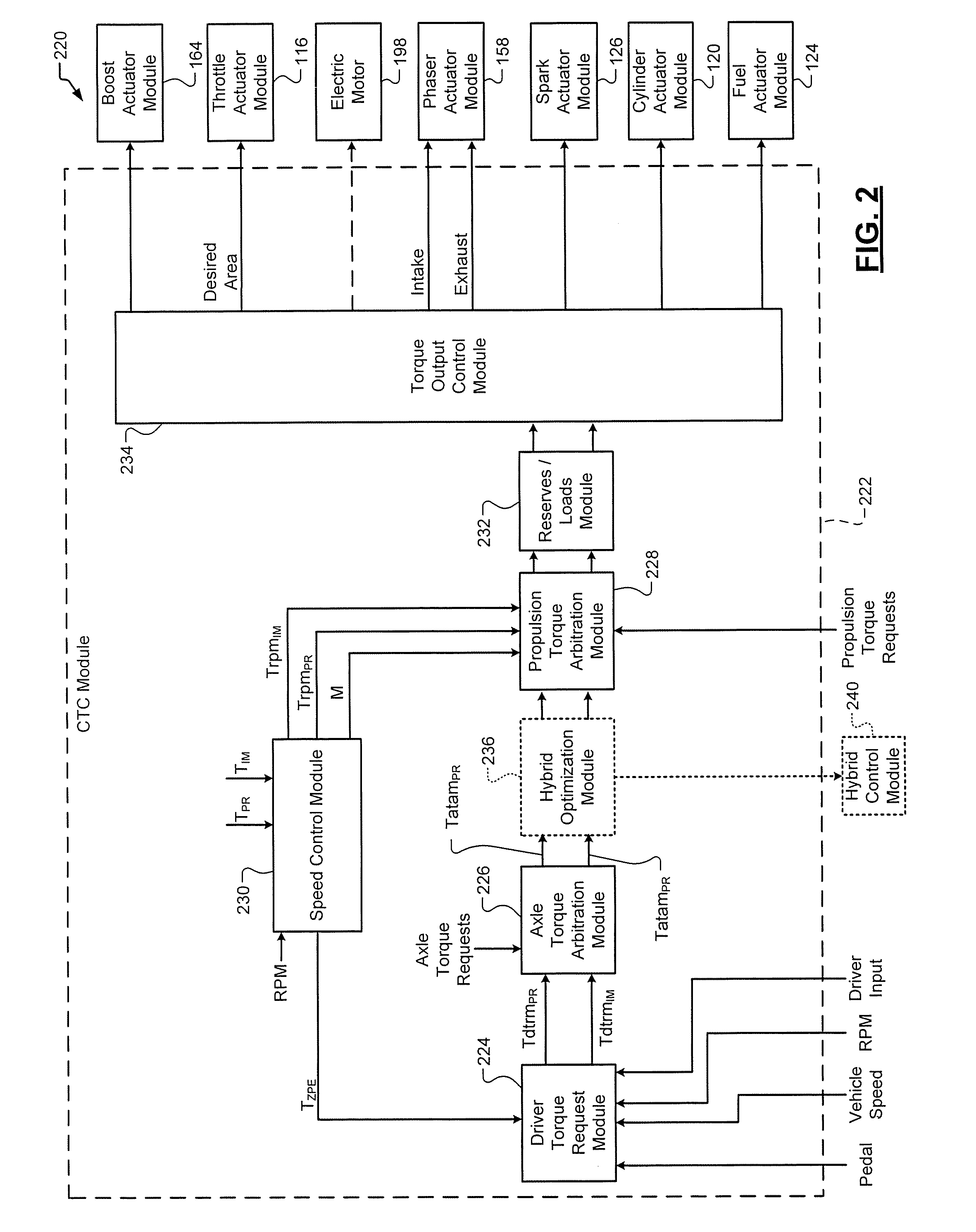
An engine control system is provided and includes a mode selection module. The mode selection module is configured to select an operating mode from one of an open loop control mode, a torque control mode, and a speed control mode based on an engine speed and a driver input. An axle torque arbitration (ABA) module generates ABA predicted and immediate torque requests based on the driver input. A speed control (SC) module generates a first set of SC predicted and immediate torque requests based on engine speed. A propulsion torque arbitration (PTA) module generates PTA predicted and immediate torque requests based on one of the ABA predicted and immediate torque requests and the first set of SC predicted and immediate torque requests based on the operating mode. A torque output control module controls output torque of an engine based on the PTA predicted and immediate torque requests.

Problems solved by technology

Traditional engine control systems, however, do not control the engine torque output as accurately as desired.
Further, traditional engine control systems do not provide as rapid of a response to control signals as is desired or coordinate engine torque control among various devices that affect the engine torque output.

Method used


Image

  • Speed control systems and methods for internal combustion engines
  • Speed control systems and methods for internal combustion engines
  • Speed control systems and methods for internal combustion engines

Examples


Embodiment Construction

The following description is merely exemplary in nature and is in no way intended to limit the disclosure, its application, or uses. For purposes of clarity, the same reference numbers will be used in the drawings to identify similar elements. As used herein, the phrase at least one of A, B, and C should be construed to mean a logical (A or B or C), using a non-exclusive logical or. It should be understood that steps within a method may be executed in different order without altering the principles of the present disclosure.

As used herein, the term module refers to an Application Specific Integrated Circuit (ASIC), an electronic circuit, a processor (shared, dedicated, or group) and memory that execute one or more software or firmware programs, a combinational logic circuit, and / or other suitable components that provide the described functionality.

Also, as used herein, the term combustion cycle refers to the reoccurring stages of an engine combustion process. For example, in a 4-str...


PUM


Abstract

An engine control system includes a mode selection module that is configured to select an operating mode from one of an open loop control mode, a torque control mode, and a speed control mode based on an engine speed and a driver input. An axle torque arbitration (ABA) module generates ABA predicted and immediate torque requests based on the driver input. A speed control (SC) module generates a first set of SC predicted and immediate torque requests based on engine speed. A propulsion torque arbitration (PTA) module generates PTA predicted and immediate torque requests based on one of the ABA predicted and immediate torque requests and the first set of SC predicted and immediate torque requests based on the operating mode. A torque output control module controls output torque of an engine based on the PTA predicted and immediate torque requests.

Description

FIELDThe present invention relates to engine control systems and more particularly to coordinated torque control and engine speed control systems.BACKGROUNDThe background description provided herein is for the purpose of generally presenting the context of the disclosure. Work of the presently named inventors, to the extent it is described in this background section, as well as aspects of the description that may not otherwise qualify as prior art at the time of filing, are neither expressly nor impliedly admitted as prior art against the present disclosure.An internal combustion engine (ICE) combusts an air / fuel mixture within cylinders to drive pistons, which produces drive torque. Air flow into an ICE engine may be regulated via a throttle and adjustment in throttle area. Adjustment in throttle area alters air flow into the ICE. As the throttle area increases, the air flow into the engine increases. Fuel injection rate is adjusted in addition to adjustment in air flow to provide ...

Claims


Application Information

Patent Timeline
Patent Type & Authority Applications(United States)
IPC IPC(8): F02M1/02
CPCB60W10/06B60W50/0097B60W50/082F02D2250/22F02D31/001F02D41/1401F02D2250/18F02D11/105B60W2540/10B60W2710/0666
Inventor KAR, KRISHNENDULIVSHIZ, MICHAELWHITNEY, CHRISTOPHER E.WILLIAMS, CHERYL A.STEWART, ETSUKO MURAJIMANNING, MATTHEW M.
Owner GM GLOBAL TECH OPERATIONS LLC
Learn More