Vehicle drive device

a drive device and drive shaft technology, applied in the direction of electric propulsion mounting, electric devices, transportation and packaging, etc., can solve the problems of restricted positioning of rotating electrical machines, restricted mounting on vehicles, and restricted device overall size in the axial direction, so as to reduce the overall axial dimension of the device and reduce the axial dimension of the support structure of the idler gears

Inactive Publication Date: 2011-06-16
AISIN AW CO LTD +1
View PDF12 Cites 29 Cited by
  • Summary
  • Abstract
  • Description
  • Claims
  • Application Information

AI Technical Summary

Benefits of technology

[0033]According to this structure, the idler gears can be supported by the common shaft by providing bearings on the inner periphery of each idler gear. Thus, as compared to the structure in which the idler gears of the two systems are supp

Problems solved by technology

Thus, the positions of the rotating electrical machines are restricted, and the overall size of the device tends to increase in the axial direction.
Thus, there are significant restrictions on mounting on vehicles, and dimensional restrictions are also significant when the rotating electrical machines are increased in size in order to improve the driving force.
Thus, a deflection angle of the axle increases due to vertical movement of the driving wheels, thereby imposing a large load on bearings that support the output members connected to the axle.
Moreover, since the positions of the rotating electrical machines are restricted to the positions c

Method used


Image

  • Vehicle drive device
  • Vehicle drive device
  • Vehicle drive device

Examples


Embodiment Construction

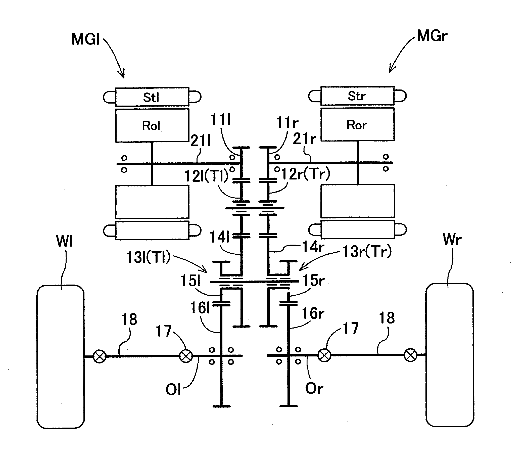
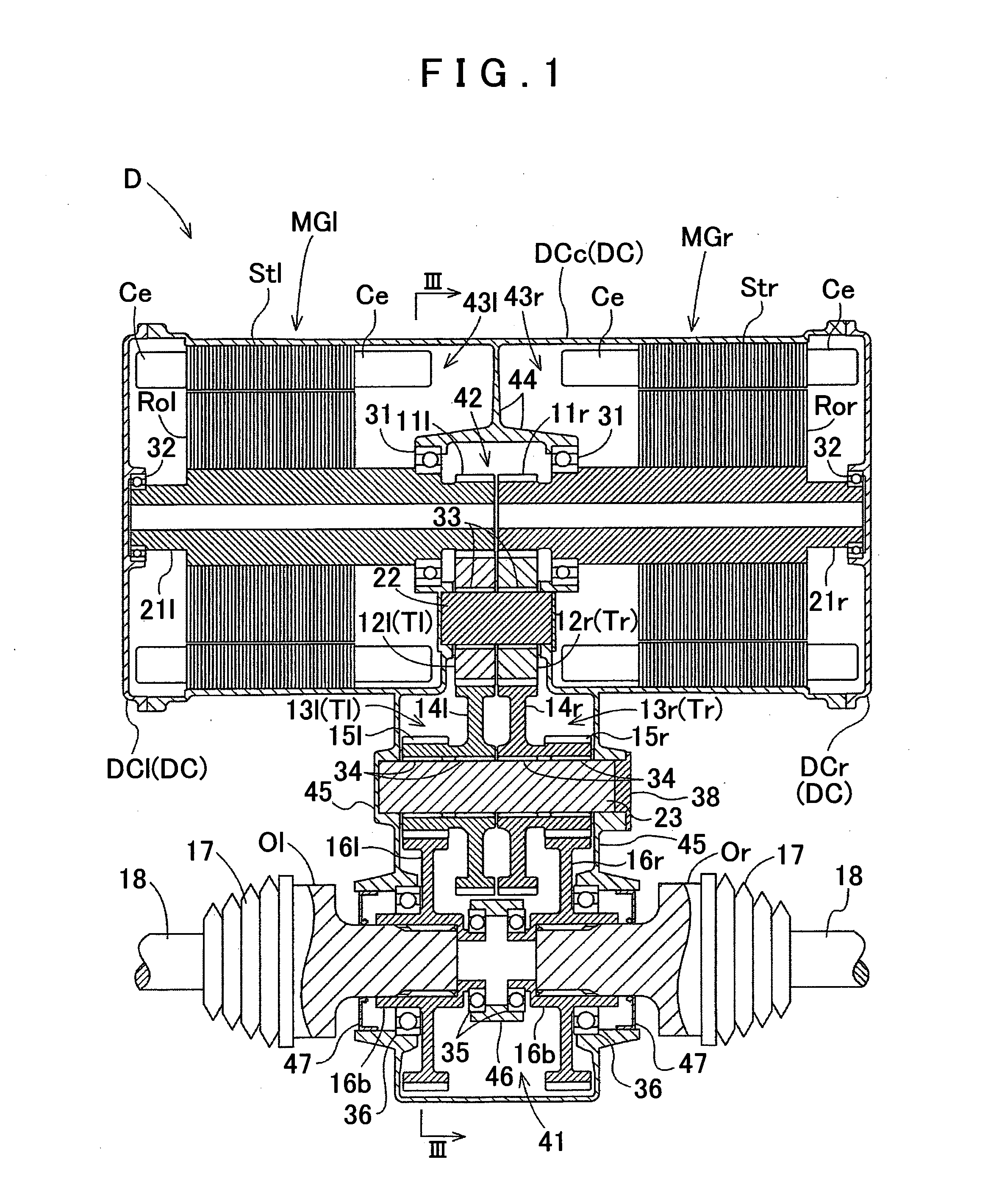
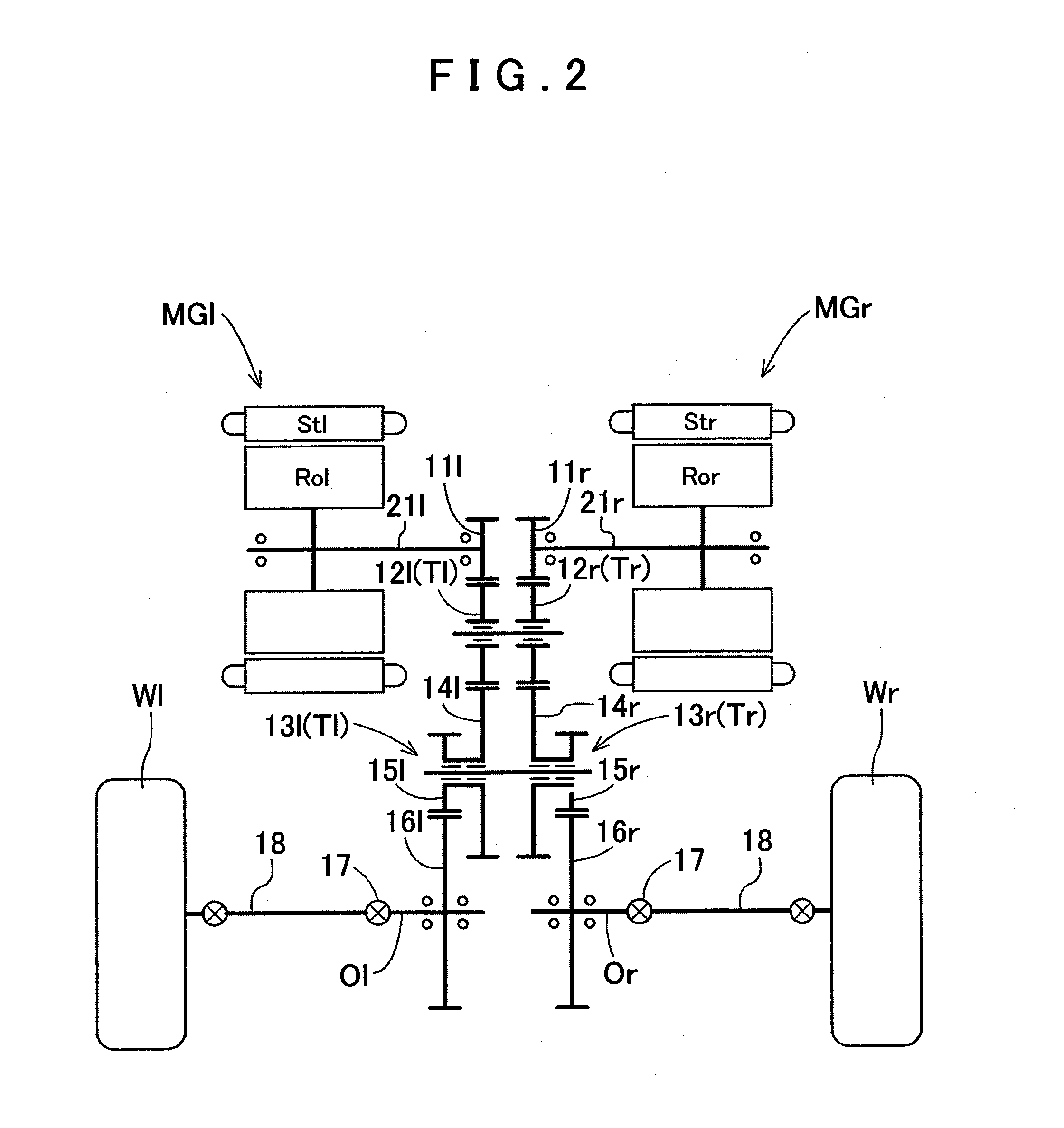
[0039]First, a vehicle drive device D according to an embodiment of the present invention will be described with reference to the accompanying drawings. The present embodiment will be described with respect to an example in which the vehicle drive device D is applied to a drive device for electric vehicles (electric cars). As shown in FIGS. 1 through 4, the vehicle drive device D of the present embodiment includes two independent systems for two driving wheels Wl, Wr, and a case DC which integrally accommodates the systems. The systems respectively include motor-generators MGl, MGr as a driving force source of a vehicle, output shafts Ol, Or respectively connected to the driving wheels Wl, Wr, and drive transmission systems Tl, Tr for respectively connecting the motor-generators MGl, MGr and the output shafts Ol, Or to each other so that driving force is transmitted therebetween. Note that, in the present embodiment, the motor-generators MGl, MGr correspond to “rotating electrical m...


PUM


Abstract

A vehicle drive device having two independent systems provided for two driving wheels, respectively, each system including a rotating electrical machine, an output member to be connected to a corresponding driving wheel, and a drive transmission system. The transmission also includes a counter deceleration mechanism, which connects the rotating electrical machine and the output member to each other. A case integrally accommodates the rotating electrical machines, the output members, and the drive transmission systems of the two systems. The rotation axes are provided so that their respective rotation axes are parallel to each other, and are positioned so as to overlap each other in the rotation axis direction. The rotating electrical machine of each system is provided with an output portion located on one side of the rotating electrical machine which is distal from the corresponding driving wheel in the rotation axis direction of the rotating electrical machine.

Description

TECHNICAL FIELD[0001]The present invention relates to the structure of drive devices for use in vehicles including a rotational electrical machine as a driving force source, such as, for example, electric vehicles and hybrid vehicles.BACKGROUND ART[0002]Various structures have been proposed regarding drive devices for vehicles including, as a driving force source, a rotating electrical machine capable of functioning as a motor, such as, for example, electric vehicles and hybrid vehicles. The structure including independent rotating electrical machines for driving two driving wheels is already known in the art.[0003]For example, a vehicle drive device described in Japanese Patent Application Publication No. JP-A-H05-116542 includes left and right output members respectively connected to left and right driving wheels, left and right rotating electrical machines respectively drivingly connected to the left and right output members, and left and right deceleration devices each formed by...

Claims


Application Information

Patent Timeline
IPC IPC(8): B60L11/00
CPCB60K1/02Y02T10/641B60K6/405B60K6/442B60K6/52B60K7/0007B60K17/043B60K2007/0038B60K2007/0061B60L2220/46H02K5/1732H02K7/006H02K7/116H02K16/00Y02T10/6234Y02T10/6265B60K6/26Y02T10/62Y02T10/64
Inventor TAKENAKA, MASAYUKITESHIMA, ATSUSHIISHIDA, RYUTAMIYAMOTO, TOMOHIKO
Owner AISIN AW CO LTD
Why Eureka
Try Eureka