Method of Crosstalk Reduction for Multi-zone Induction Heating Systems

Active Publication Date: 2011-06-16
HONEYWELL ASCA INC
View PDF9 Cites 1 Cited by
  • Summary
  • Abstract
  • Description
  • Claims
  • Application Information

AI Technical Summary

Benefits of technology

[0007]It is therefore an object of the present invention to reduce crosstalk in a multi-zo

Problems solved by technology

Since a high frequency current is applied to each work coil to develop the inductive field used to heat the work load, such field developed by one work coil may in part pass through the core of a neighboring work coil

Method used


Image

  • Method of Crosstalk Reduction for Multi-zone Induction Heating Systems
  • Method of Crosstalk Reduction for Multi-zone Induction Heating Systems
  • Method of Crosstalk Reduction for Multi-zone Induction Heating Systems

Examples


Example

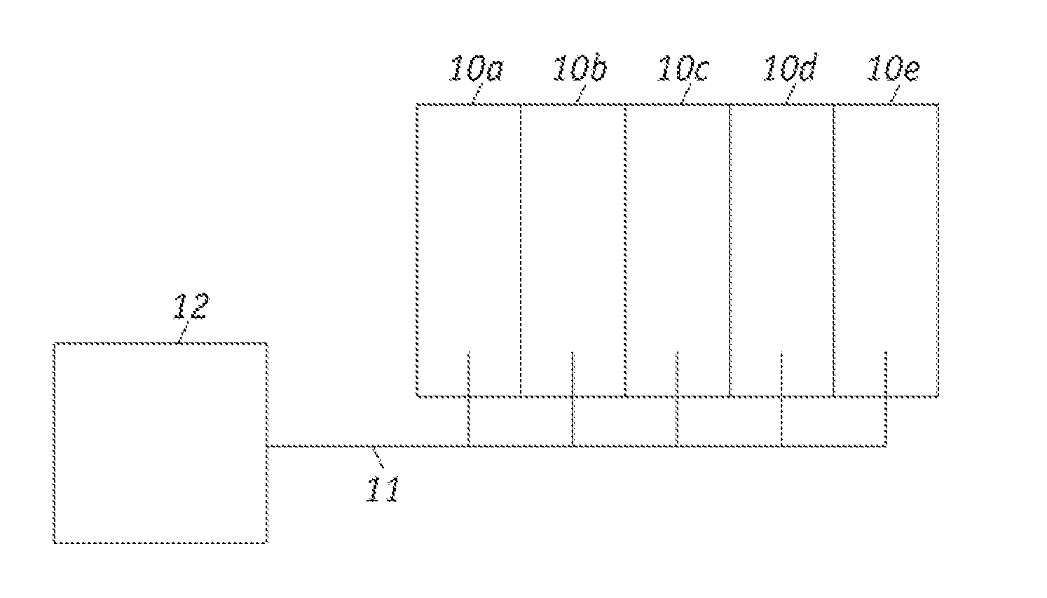
[0017]Referring now to FIG. 1, a typical induction heating apparatus includes, inter alia, a power module 10, which may be exemplarily divided into five power module sections 10. It is to be recognized that any number of power module sections may be used and therefor any such number is within the scope of the present invention.

[0018]As is well known in the art, each section 10a-e of the power module 10 is associated with a segment of an induction work coil (not shown) to be operatively associated with a respective zone of the work load (not shown). Also as is well known in the art, each of the power module sections 10a-e develop the work coil currents for its associated work coil.

[0019]In accordance with the present invention, a common synchronizing signal 12 is sent to each of the power module sections 10a-e. Exemplarily, the synchronizing signal may be high precision synchronization pulses. The synchronizing signal may be communicated wirelessly or via a wire 11. The synchronizing...


PUM


Abstract

Reduction of crosstalk between induction heating coils in an induction heating apparatus and particularly to reduction of crosstalk in a multi-zone induction heating system provides greater reliability for the power modules.

Description

RELATED APPLICATION DATA[0001]The present application is claims priority under 35 U.S.C. §119(e) to co-pending application for Method of Crosstalk Reduction for Multi-zone Induction Heating Systems, Application No. 61 / 286,798 filed Dec. 16, 2009, which is incorporated herein by reference.TECHNICAL FIELD OF THE INVENTION[0002]The present invention generally relates generally to induction heating apparatus and, more particularly, to methods for reducing crosstalk between induction heating coils in such heating apparatus.BACKGROUND OF THE INVENTION[0003]In typical induction heating systems, accurate and close control of the operating temperature of the workload is generally required. Moreover, it may become necessary for various sections of the workload to require different levels of heating such that each section of the workload must be closely controlled for accuracy.[0004]For example, Simcock, U.S. Pat. No. 5,059,762, discloses a multi-zone induction heating system which includes a ...

Claims


Application Information

Patent Timeline
IPC IPC(8): H05B6/04
CPCH05B6/065
Inventor DOHMEIER, NICHOLASMCCORMICK, KEITH
Owner HONEYWELL ASCA INC
Why Eureka
Try Eureka