Permanent magnet motor

a permanent magnet, motor technology, applied in the direction of dynamo-electric machines, magnetic circuit shapes/forms/construction, structural associations, etc., can solve the problem of not being able to install the motor easily

Active Publication Date: 2011-06-16
JOHNSON ELECTRIC SA
View PDF9 Cites 22 Cited by
  • Summary
  • Abstract
  • Description
  • Claims
  • Application Information

AI Technical Summary

Problems solved by technology

However, the housing with curved side portions makes it not easy to install the motor.

Method used


Image

  • Permanent magnet motor
  • Permanent magnet motor
  • Permanent magnet motor

Examples


second embodiment

[0036]An end cap as shown in FIG. 7 and FIG. 8, further comprises two chokes 49 and 50. The first choke 49 is electrically connected in series between the first terminal 45 and the thermistor 47. The second choke 50 is electrically connected in series between the second terminal 46 and the second brush 42 by the conductor 44 and the brush holder and brush leaf of the second brush 42. The end cap 31 has better EMI (Electro-Magnetic Interference) suppression due to the addition of the two chokes.

third embodiment

[0037]Another motor according to the present invention is illustrated in FIG. 9. This motor further comprises an end cap cover 51 that is mounted to the end cap 31 in the axial direction, to provide additional functions. FIG. 10 illustrates the cup-shaped cover 51 and FIG. 11 is an end view of the cover 51. FIG. 12 is an end view of the assembled cover 51 and end cap 31 and FIG. 13 is a longitudinal sectional view of the assembled cover 51 and end cap 31.

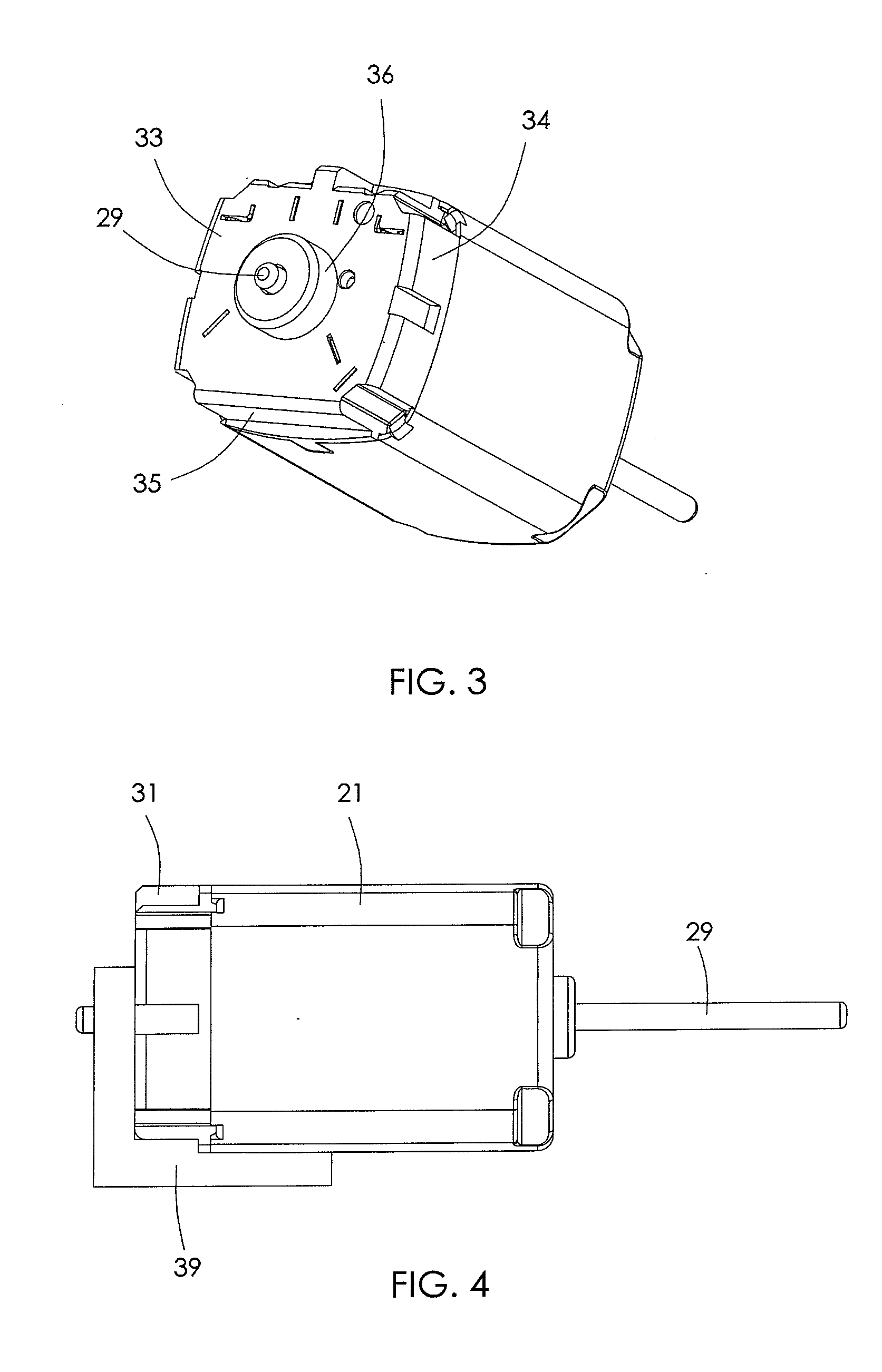
[0038]The cup-shaped cover 51 comprises a bottom 52 and four side walls 53 extending axially from the edge of the bottom 52. One of the side walls 53 is substantially flat and is aligned with the flat mounting surface 35 of the cover 31 (FIG. 12). Four legs 54 are integrally formed with the cover 51 and extend axially from respective corners of the cover 51. As shown in FIG. 9, four guiding grooves 37 are formed at the corners of the end cap 31 for frictionally receiving the four legs 54 to guide the mounting of the cover 51 to the ...


PUM


Abstract

A permanent magnet motor has a stator and a rotor rotatably mounted to the stator. The stator has a housing with n side portions and n connecting portions distributed alternately, wherein n is a integer equal to or greater than 3. Adjacent side portions are interconnected by one of the connecting portions. The radial cross section of each side portion is a convex curved line which is curved outwardly relative to a straight line passing through the two ends of the convex curve line. Permanent magnets are fixed to an inner surface of the housing. An end cap fixed to one end of the housing, has a bottom and n side walls extending from the bottom. A flat mounting surface is formed at the outer surface of a first one of the side walls.

Description

CROSS REFERENCE TO RELATED APPLICATIONS[0001]This non-provisional patent application claims priority under 35 U.S.C. §119(a) from Patent Application No. 200910188901.7 filed in The People's Republic of China on Dec. 11, 2009.FIELD OF THE INVENTION[0002]This invention relates to a permanent magnet motor, and in particular to a miniature permanent magnet direct current (PMDC) motor, such as a motor for vehicle door lock system or a vehicle lift gate system.BACKGROUND OF THE INVENTION[0003]The size of a PMDC motor is a very critical factor in some applications. There is a desire for a smaller motor having equal or increased performance. In other words, there is a desire for a motor having a higher power density. U.S. published patent application No. US-2010-0231072-A1 discloses a PMDC motor having increased power density compared with a traditional flat sided motor. The motor comprises a housing made of steel and having four side portions and four connecting portions. Adjacent side por...

Claims


Application Information

Patent Timeline
Patent Type & Authority Applications(United States)
IPC IPC(8): H02K11/02H02K5/04
CPCH02K1/17H02K5/00H02K11/026H02K5/145H02K11/0021H02K5/04H02K11/215
Inventor WONG, BEN TO FANZHANG, HONG WEILIAO, TIAN JUN
Owner JOHNSON ELECTRIC SA
Why Eureka
Try Eureka