
Low Noise Rotor or Stator of an Electric Motor or Generator and Method of Assembling the Same

a low-noise, electric motor-type technology, applied in the direction of stator/rotor body manufacturing, machine/engine, magnetic circuit shape/form/construction, etc., can solve the problems of vibration within the rotor and undesirable audible noise, and achieve the effect of reducing or inhibiting the relative movement and vibration of the teeth

Active Publication Date: 2011-06-16
NIDEC MOTOR CORP
View PDF6 Cites 22 Cited by
  • Summary
  • Abstract
  • Description
  • Claims
  • Application Information

AI Technical Summary

Benefits of technology

[0008]The present invention is aimed at reducing or inhibiting relative movement and vibration of the teeth of stators and rotors. This is achieved by mechanically connecting the free ends of the teeth to each other and / or by stiffening the body portion of the core via one or more welds.
[0011]In yet another aspect of the invention, a method of forming a stator or rotor of an electric motor or generator comprises forming a core of the stator or rotor. The core is formed of ferromagnetic material and has a circular body portion and a plurality of teeth. The circular body portion defines a central axis. The axis defines radial and circumferential directions. The teeth are arranged circumferentially about the axis and extending radially outward from the circular body portion. The circular body portion comprises a plurality of interior surfaces that face toward the axis. A slit extends between a pair of the interior surfaces and extends radially outward partially through the circular body portion. The slit has a pair of opposing faces. The method also comprises a step of welding at least portions of the opposing faces of the slit to each other in a manner limiting relative movement between the pair of the interior surfaces and increasing the stiffness of the core.

Problems solved by technology

This causes vibration within the rotor or stator, which in turn generates undesirable audible noise.

Method used


Image

  • Low Noise Rotor or Stator of an Electric Motor or Generator and Method of Assembling the Same
  • Low Noise Rotor or Stator of an Electric Motor or Generator and Method of Assembling the Same
  • Low Noise Rotor or Stator of an Electric Motor or Generator and Method of Assembling the Same

Examples


Embodiment Construction

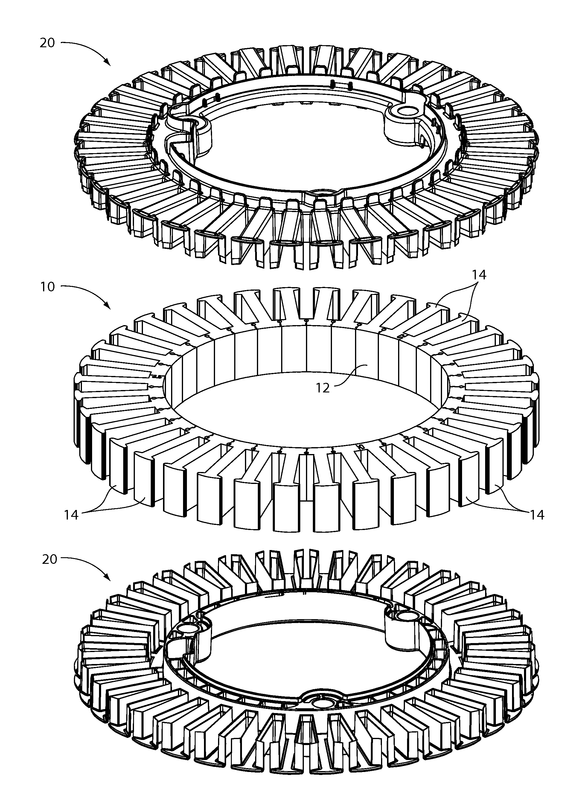
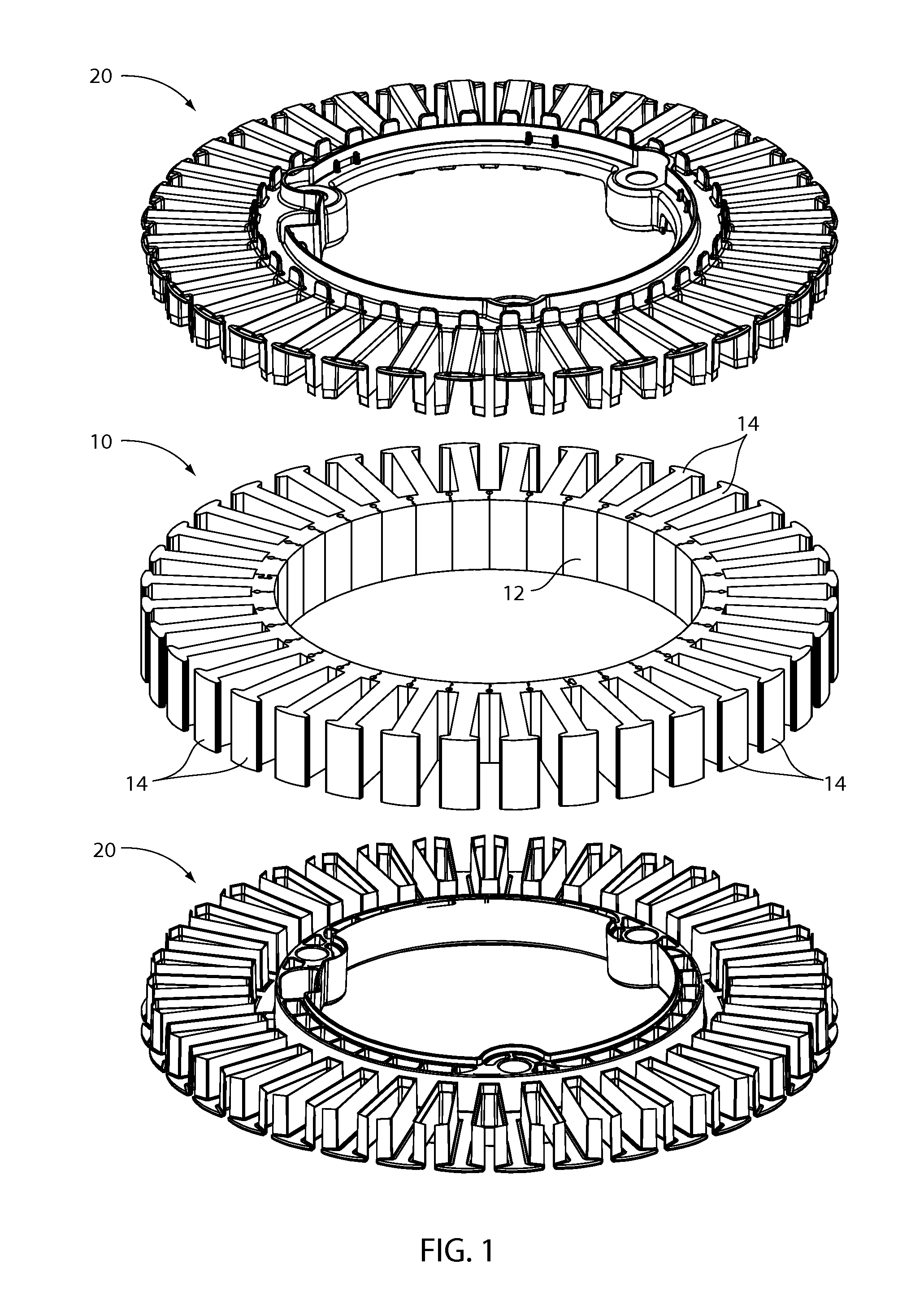
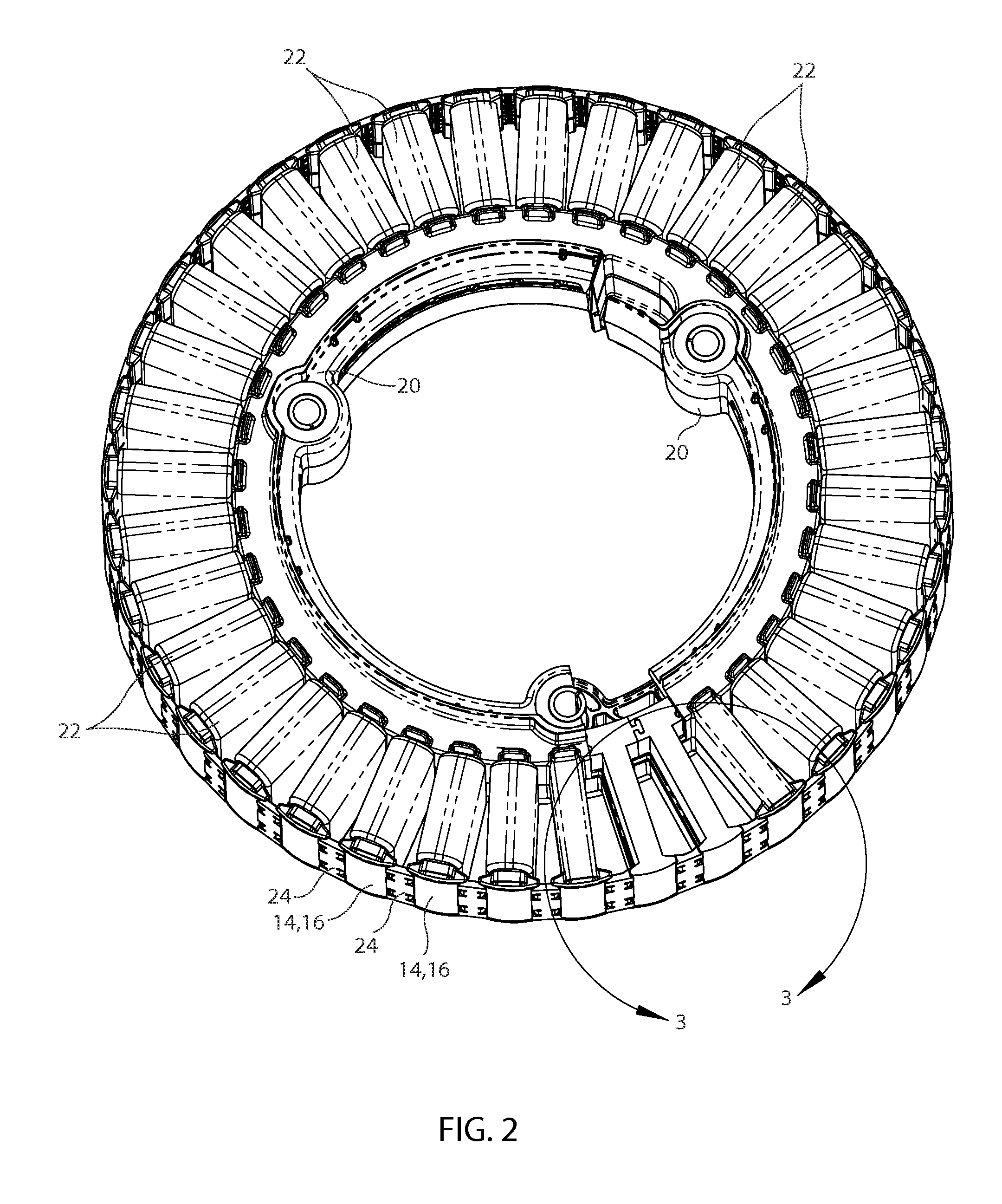
[0024]An exemplary embodiment of a core of a stator or rotor in accordance with the invention is shown in FIG. 1 along with insulating shrouds that encase the core. The core 10 is formed of ferromagnetic material and is preferably in the form of a stack of laminations or spirally overlaid laminations. The core 10 has a generally circular body 12 (in this case a ring shaped body) and a plurality of teeth 14 that extend radially from the circular body (in this case radially outward). Each tooth 14 has an end portion 16 opposite the circular body 12 and an intermediate portion 18 that extends from the circular body to the end portion. The intermediate portion 18 of each tooth 14 perpendicularly bisects the tooth's end portion 16 in a manner giving the tooth a T-shaped configuration. Together the insulating shrouds 20 encase the core 10 and electrically shield the core from the windings 22. Each winding 22 (represented by a generally toroidal element in the figures) encircles the interm...


PUM


Abstract

A stator or rotor of an electric motor or generator comprises a core formed of ferromagnetic material having a plurality of teeth arranged circumferentially about an axis. In one aspect of the invention, at least one retaining member connects the end portions of at least two of the teeth to each other in a manner inhibiting relative movement between said tooth end portions. By inhibiting relative movement between said tooth end portions, vibration is reduced. Vibration can also be reduced by welding interior surfaces of a core to each other. Reducing the vibration reduces the noise emissions of the rotor or stator during operation.

Description

CROSS-REFERENCE TO RELATED APPLICATIONS[0001]This application claims priority to U.S. Provisional Patent Application Ser. No. 61 / 286,305, filed on Dec. 14, 2009, which is hereby incorporated by reference in its entirety.STATEMENT REGARDING FEDERALLY SPONSORED RESEARCH OR DEVELOPMENT[0002]Not Applicable.APPENDIX[0003]Not Applicable.BACKGROUND OF THE INVENTION[0004]1. Field of the Invention[0005]This invention pertains generally to electric motors and generators. More specifically, this invention pertains to the reduction of noise generated by a stator or rotor, which is partially caused by relative movement between the teeth of the rotor or stator as teeth pass through non-constant magnetic flux fields. The invention increases the stiffness between the teeth in a manner inhibiting the relative movement.[0006]2. General Background[0007]Electric motors and generators are primarily comprised of a rotor and a stator. The stator may encircle the rotor or vice versa. Alternatively, the rot...

Claims


Application Information

Patent Timeline
IPC IPC(8): H02K1/18H02K15/02
CPCH02K1/148H02K3/522H02K3/527Y10T29/49012Y10T29/49009Y10T29/49316F01D9/00F01D9/042H02K3/30
Inventor HORST, GARY E.BOHRER, JEFFREY R.BAILEY, DANIEL E.HILTON, DANIEL E.LEVINE, GREGORY M.KLEIN, BRIAN P.DOHOGNE, L. RANNEY
Owner NIDEC MOTOR CORP
Learn More