Electronic Component Device and Method for Manufacturing the Same
- Summary
- Abstract
- Description
- Claims
- Application Information
AI Technical Summary
Benefits of technology
Problems solved by technology
Method used
Image
Examples
first embodiment
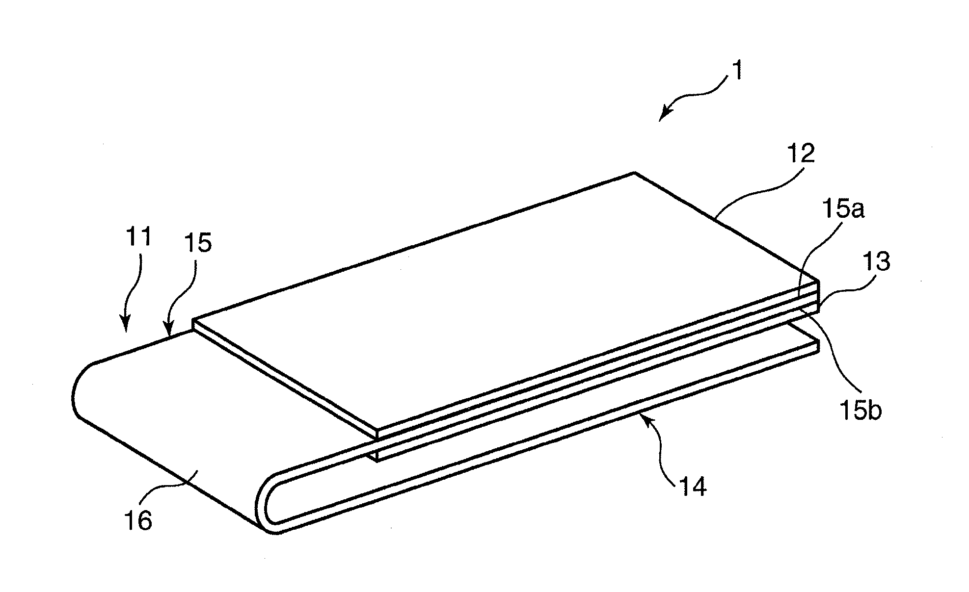
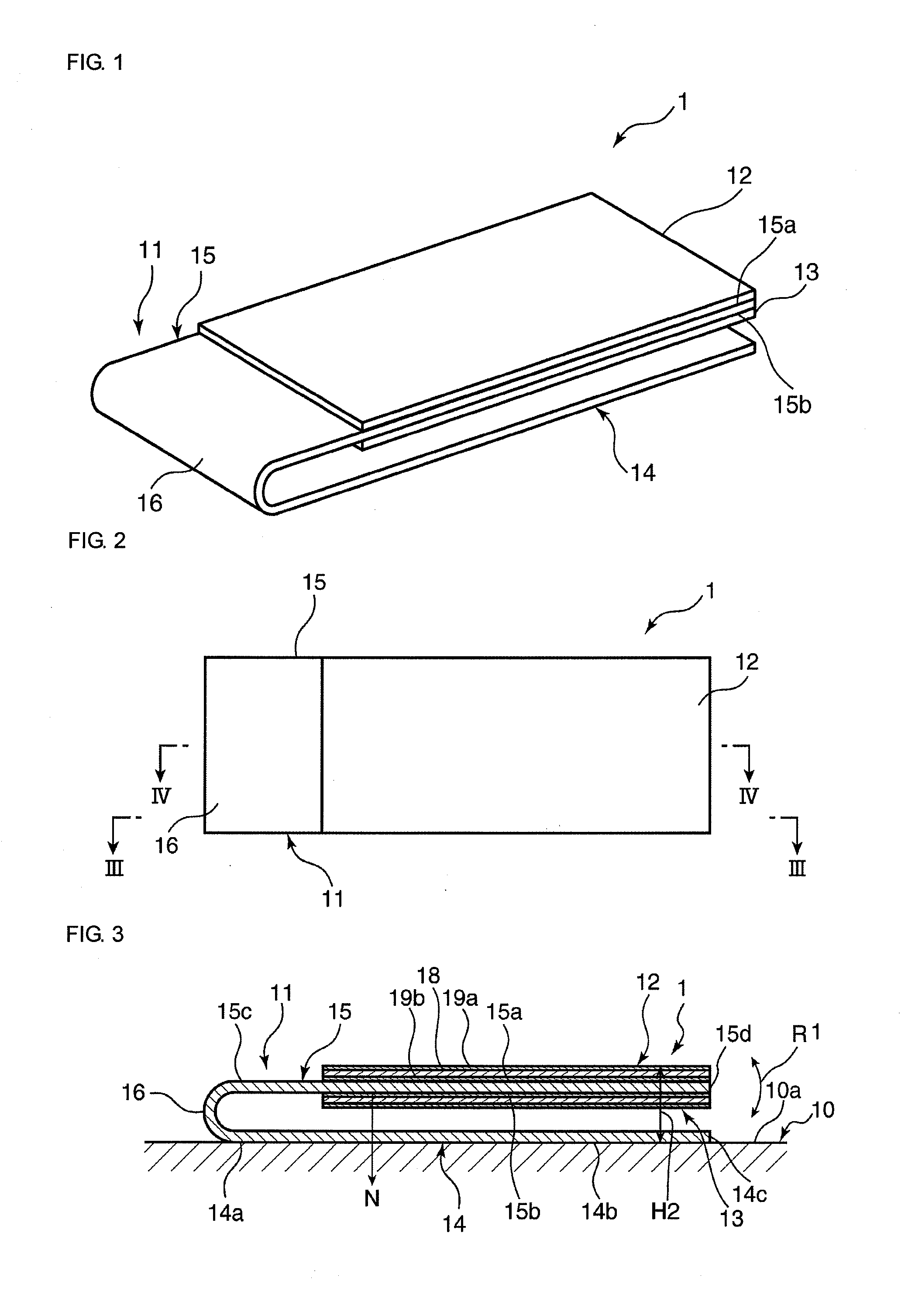
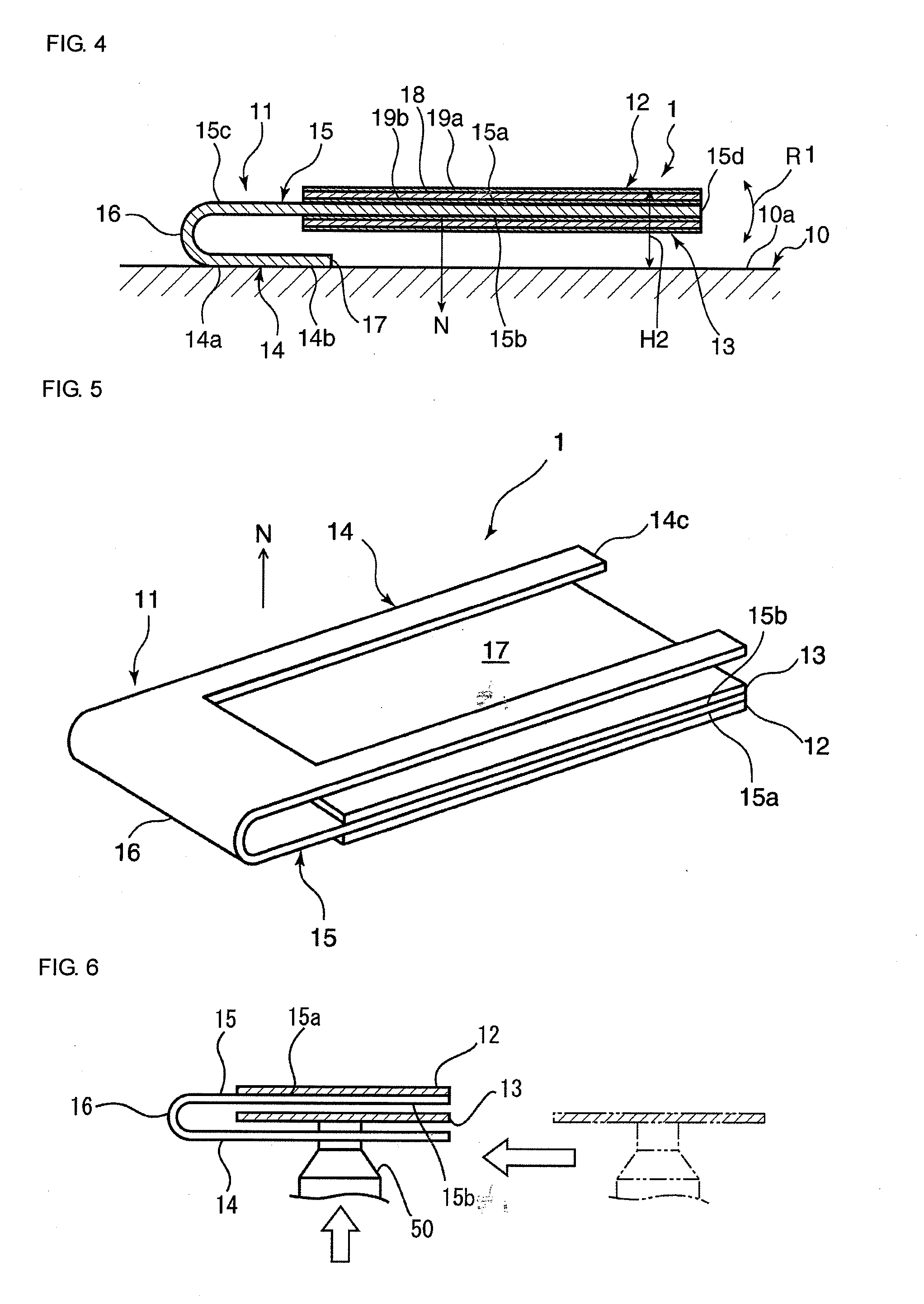
[0042]FIG. 1 is a schematic perspective view of a vibratory device 1 of the present embodiment. FIG. 2 is a schematic plan view of the vibratory device 1. FIG. 3 is a schematic cross-sectional view of the vibratory device 1 along the cut line III-III illustrated in FIG. 2. FIG. 4 is a schematic cross-sectional view of the vibratory device 1 along the cut line IV-IV illustrated in FIG. 2.
[0043]As illustrated in FIG. 3, the vibratory device 1 is a device fixed to a fixation member 10 and used for transmitting vibration to the fixation member 10. The fixation member 10 is not particularly limited. The fixation member 10 can be a casing of a cellular phone, for example. That is, the vibratory device 1 can be used in a vibrator of a cellular phone, for example.
[0044]As illustrated in FIG. 1, the vibratory device 1 includes an elastic plate 11, a first piezoelectric diaphragm 12, and a second piezoelectric diaphragm 13. The elastic plate 11 includes integrally formed plate-like fixable po...
second embodiment
[0067]For the above first embodiment, an example in which the cut portion 17 of the fixable portion 14 forms a section that does not overlap the fixable portion 14 in the second piezoelectric diaphragm 13 in the normal direction N is described. However, the present invention is not limited to this configuration.
[0068]For example, as illustrated in FIG. 7, the second piezoelectric diaphragm 13 may include a section that does not overlap the fixable portion 14 in the normal direction N by making the length Li between the first end of the fixable portion 14 in its planar direction, the end being adjacent to the connection portion 16, and the second end 14c shorter than the length L2 between the first end of the vibratory portion 15 in its planar direction, the end being adjacent to the connection portion 16, and the second end 15d. Even in this case, the mounting nozzle 50 can be positioned in the normal direction N of the vibratory portion 15. Thus, the second piezoelectric diaphragm ...
third embodiment
[0077]FIG. 14 is a schematic cross-sectional view of a vibratory device 1c of a third embodiment. FIG. 15 is an illustration taken along the line XV-XV in FIG. 14. As illustrated in FIG. 15, for the present embodiment, the fixable portion 14 is fixed to the fixation surface 10a of the fixation member 10 such that a flexible printed board 51 attached to the fixable surface 14b is disposed therebetween. As illustrated in FIG. 15, the flexible printed board 51 is provided with a driving circuit 52 for the first and second piezoelectric diaphragms 12 and 13, the driving circuit 52 being electrically coupled to the electrodes 19a and 19b. The driving circuit 52 is positioned within the cut portion 17. The driving circuit 52 is fixed on the fixation member 10 so as to overlap the second piezoelectric diaphragm 13 and so as not to overlap the fixable portion 14 in the normal direction N.
[0078]In this way, arranging the driving circuit 52 so as to overlap the second piezoelectric diaphragm ...
PUM
 Abstract
Description
Claims
Application Information
 - R&D
- Intellectual Property
- Life Sciences
- Materials
- Tech Scout
- Unparalleled Data Quality
- Higher Quality Content
- 60% Fewer Hallucinations
Browse by: Latest US Patents, China's latest patents, Technical Efficacy Thesaurus, Application Domain, Technology Topic, Popular Technical Reports.
© 2025 PatSnap. All rights reserved.Legal|Privacy policy|Modern Slavery Act Transparency Statement|Sitemap|About US| Contact US: help@patsnap.com


