Digital-to-analog converter
- Summary
- Abstract
- Description
- Claims
- Application Information
AI Technical Summary
Benefits of technology
Problems solved by technology
Method used
Image
Examples
first exemplary embodiment
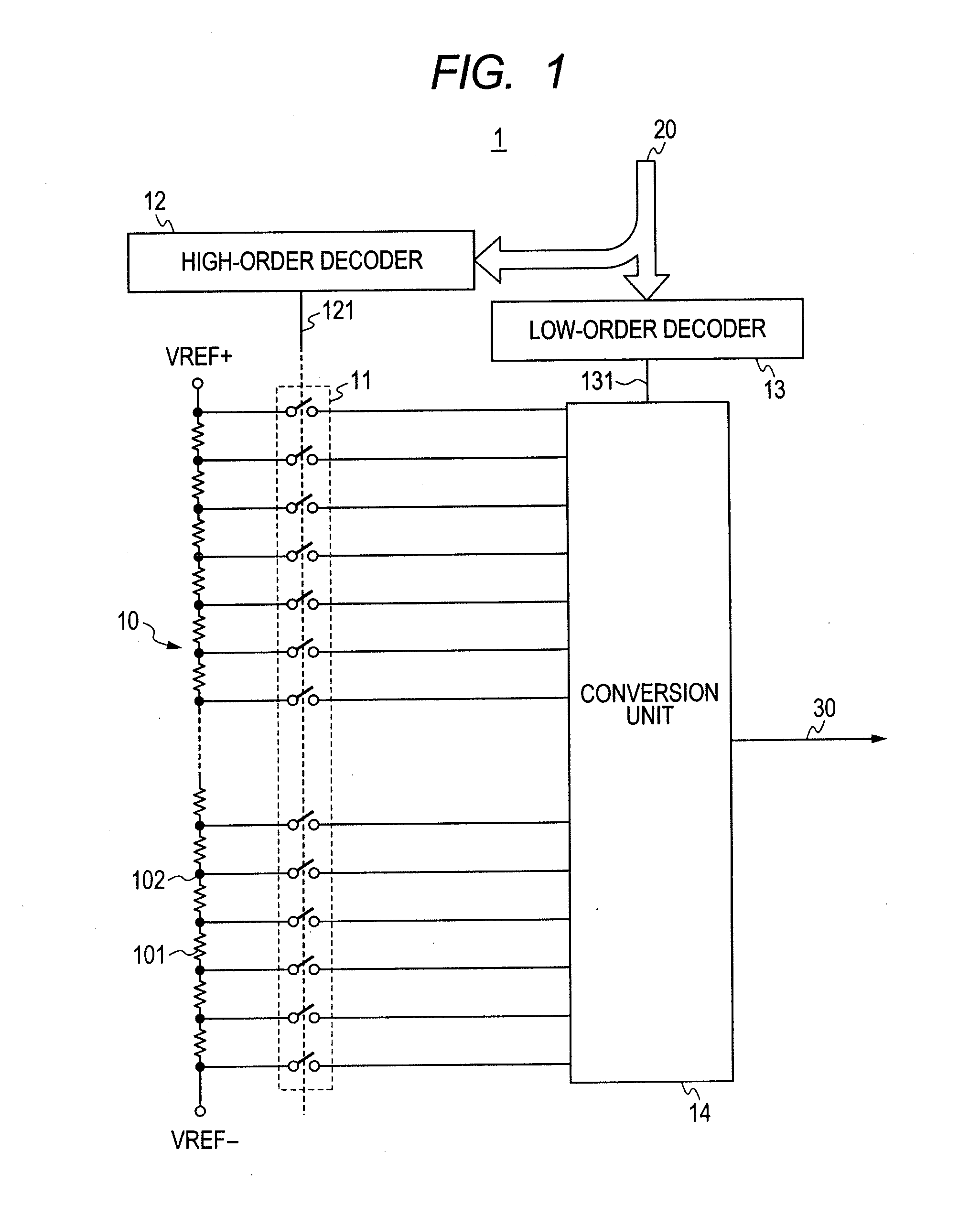
[0027]FIG. 1 shows a resistor string digital-to-analog converter according to a first exemplary embodiment. The resistor string digital-to-analog converter 1 includes a high-order resistor string 10, first high-order switches 11, a high-order decoder 12, a low-order decoder 13, and a conversion unit 14.
[0028]The high-order resistor string 10 includes a plurality of voltage acquisition points 102, which are coupled through unit resistors 101. The high-order resistor string 10 is divided by the unit resistors 101, which are series-coupled between a first reference voltage (e.g., high-potential reference voltage VREF+) and a second reference voltage (e.g., low-potential reference voltage VREF−). Thus, a plurality of high-order analog voltages are generated and output from the voltage acquisition points 102. Although the configuration shown in FIG. 1 is such that one unit resistor 101 is provided between the voltage acquisition points 102, the number of unit resistors 101 between the vo...
second exemplary embodiment
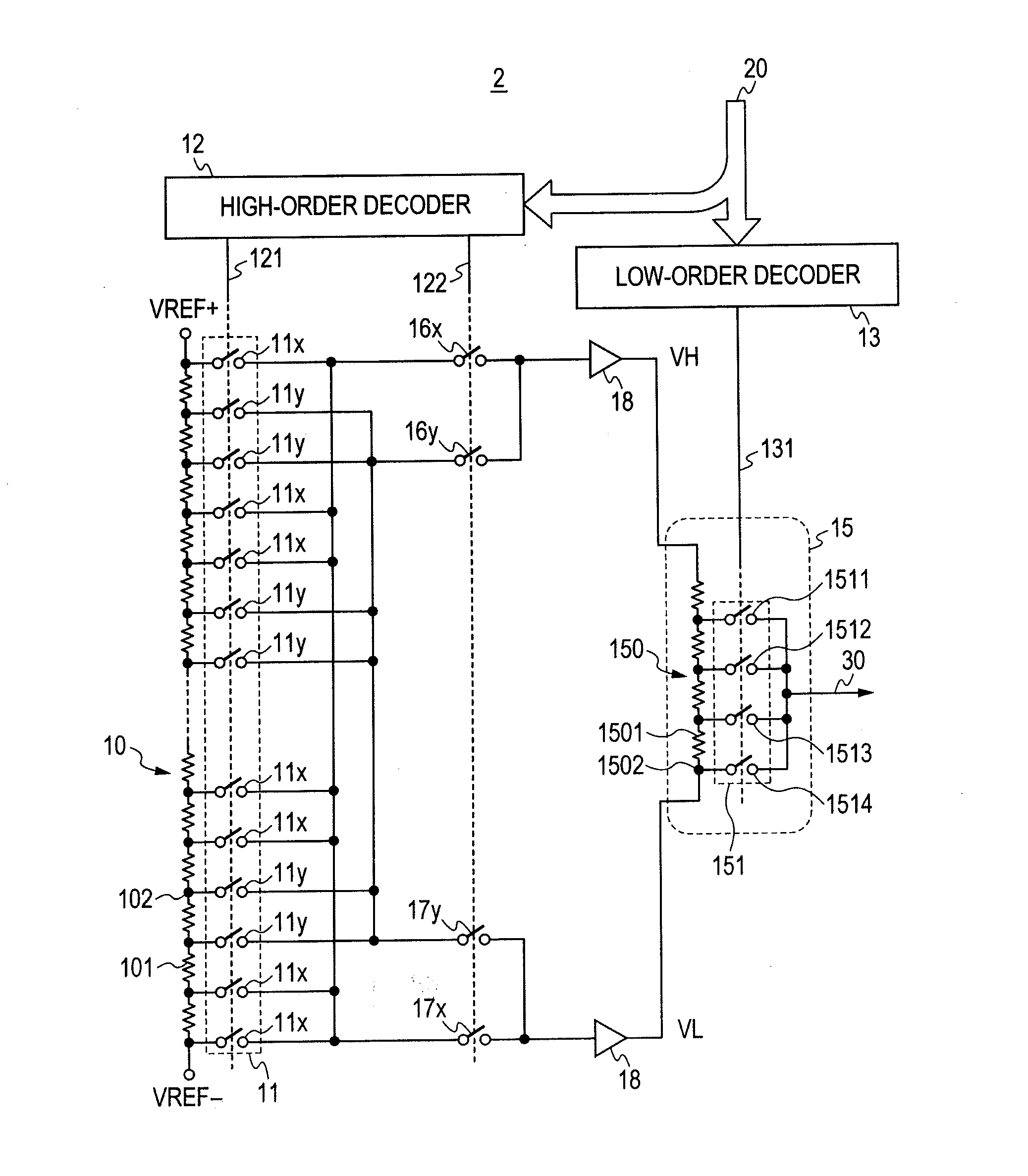
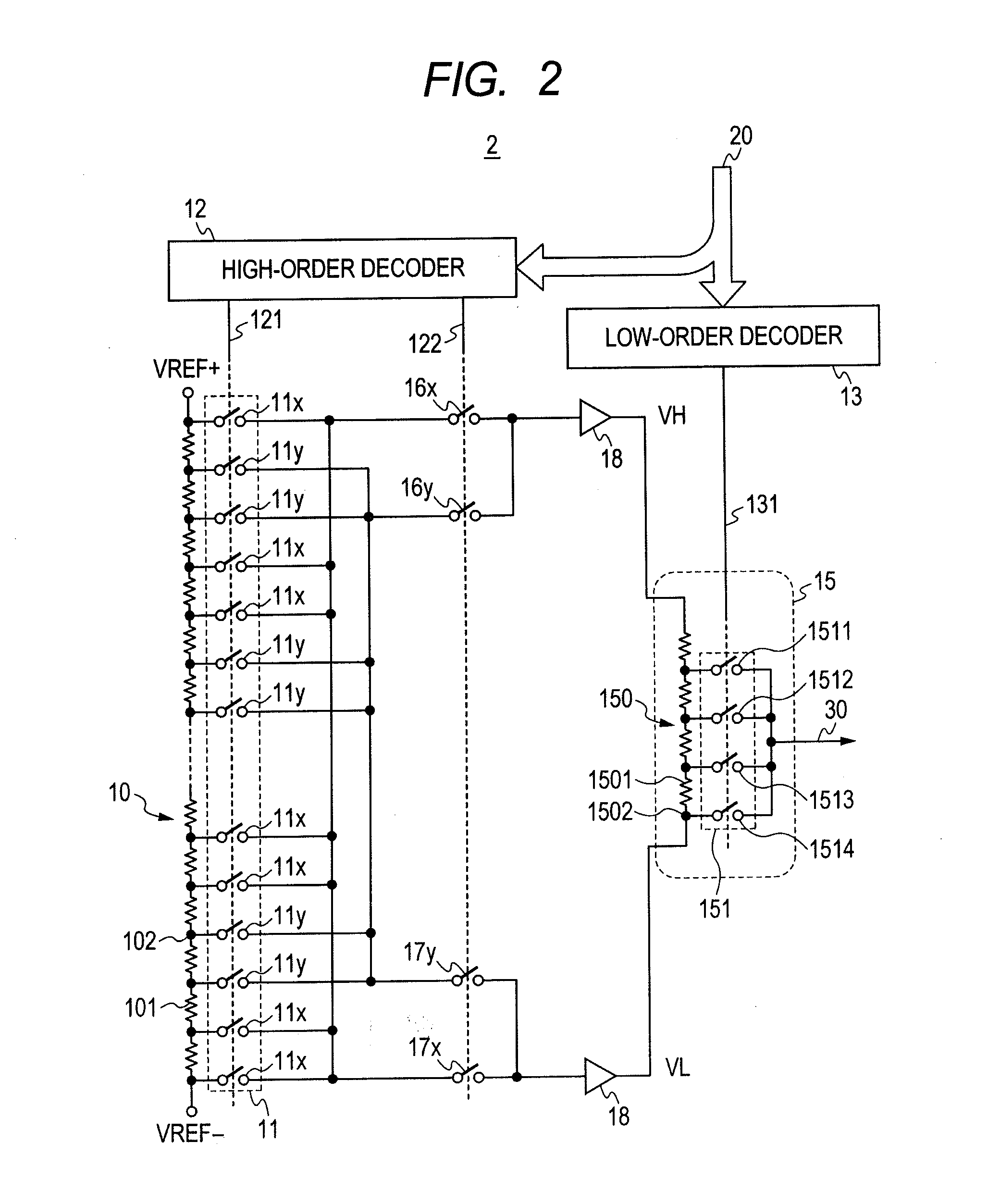
[0037]A second exemplary embodiment of the present invention will now be described. A digital-to-analog converter 2 according to the second exemplary embodiment includes a high-order resistor string 10, first high-order switches 11x, 11y, a high-order decoder 12, a low-order decoder 13, a low-order resistor string digital-to-analog converter 15, second high-order switches 16x 16y, 17x, 17y, and a buffer 18. By way of example, it is assumed that the resistor string digital-to-analog converter shown in FIG. 2 handles a 10-bit digital input signal 20, which has nine high-order bits and one low-order bit.
[0038]The high-order resistor string 10 has the same configuration as shown in FIG. 1. A plurality of unit resistors are series-coupled to divide a portion between the reference voltages VREF+, VREF− so that a pair of high-order analog voltages are generated and output from voltage acquisition points 102. In the present exemplary embodiment, the nine high-order bits enter the high-order...
third exemplary embodiment
[0071]A third exemplary embodiment of the present invention will now be described. FIG. 7 is a diagram illustrating an example configuration of a resistor string digital-to-analog converter 3 according to the third exemplary embodiment. The resistor string digital-to-analog converter 3 shown in FIG. 7 includes a high-order resistor string 10, first high-order switches 11, a high-order decoder 12, a low-order decoder 13, and an interpolating amplifier 19. The present exemplary embodiment will be described on the assumption that the digital input signal 20 is of a 10-bit type, divided into nine high-order bits and three low-order bits, and subjected to digital-to-analog conversion. In this instance, the two lowest-order bits of the nine high-order bits are duplicates of the two highest-order bits of the three low-order bits. The third exemplary embodiment differs from the second exemplary embodiment in the configuration of the high-order resistor string 10. More specifically, the firs...
PUM
 Abstract
Description
Claims
Application Information
 - R&D
- Intellectual Property
- Life Sciences
- Materials
- Tech Scout
- Unparalleled Data Quality
- Higher Quality Content
- 60% Fewer Hallucinations
Browse by: Latest US Patents, China's latest patents, Technical Efficacy Thesaurus, Application Domain, Technology Topic, Popular Technical Reports.
© 2025 PatSnap. All rights reserved.Legal|Privacy policy|Modern Slavery Act Transparency Statement|Sitemap|About US| Contact US: help@patsnap.com


