Gaze target determination device and gaze target determination method

a target determination and gaze technology, applied in the field of gaze target determination devices, can solve the problems of limited detection range of eye gaze, inability to directly measure, and limitation of corneal reflex methods in user's posture or standing position, and achieve the effect of accurate object determination

Active Publication Date: 2011-06-16
PANASONIC INTELLECTUAL PROPERTY CORP OF AMERICA
View PDF7 Cites 56 Cited by
  • Summary
  • Abstract
  • Description
  • Claims
  • Application Information

AI Technical Summary

Benefits of technology

[0040]With such a structure, it is possible to obtain the same advantageous effects as those of the gaze target determination device.
[0041]Further, a method for determining a gaze target according to an aspect of the present invention is a method for determining an object at which a user is gazing from among a plurality of objects displayed on a screen. The method includes: generating a display event for each of the objects at different times, the display event triggering a movement of a gaze direction of the user who is gazing at the object, the display event indicating at least one of a movement and a change of at least part of the object; detecting the gaze direction of the user; calculating a gaze trajectory that is time series data of the gaze direction, based on the gaze direction detected in the detecting of the gaze direction of the user; detecting an event detection time which is a time at which the gaze direction moves according to the display event, based on the gaze trajectory calculated in the calculating of a gaze trajectory; calculating, for each of the objects, a time difference between the event detection time detected in the detecting of an event detection time and an event occurrence time that is a time at which the display event is generated in the generating; and determining the object at which the user is gazing from among the objects, based on the time difference calculated in the calculating of a time difference.
[0043]Note that the present invention can also be implemented as a program causing a computer to execute the respective steps included in the gaze target determination method. Such a program may be distributed, of course, via recording medium such as a CD-ROM (Compact Disc Read Only Memory) and communication medium such as the Internet.
[0044]With a gaze target determination device according to an aspect of the present invention, it is possible to determine the gaze target of the user based on time difference between event detection time and event occurrence time. This allows accurate determination of the object at which the user is gazing from among a plurality of objects displayed on a screen.

Problems solved by technology

However, in the corneal reflex method, infrared light needs to be irradiated on the eye area; and thus, the detection range of the eye gaze is limited to the range where the infrared light can be irradiated.
Thus, the corneal reflex method has a limitation in the user's posture or standing position where the eye gaze direction can be detected.
In the method disclosed in Non Patent Literature 1, it is not possible to directly measure the center position of an eyeball, the radius of the eyeball, or the like; and thus, parameters such as the eye center position or the radius of the eye are modeled using facial features.
On the other hand, a disadvantage also exists where a relatively large error may occur between the line connecting the eyeball center and the iris center and the actual eye gaze due to an error in calibration for the user or an error in the facial feature detection.
However, in this type of method, the estimation accuracy of the gaze direction is still not significantly improved.
As described, in the case where the user takes various postures freely to some extent, the estimated gaze direction includes a relatively large error.

Method used


Image

  • Gaze target determination device and gaze target determination method
  • Gaze target determination device and gaze target determination method
  • Gaze target determination device and gaze target determination method

Examples


Embodiment Construction

[0070]Hereinafter, an embodiment of the present invention is described with reference to the drawings.

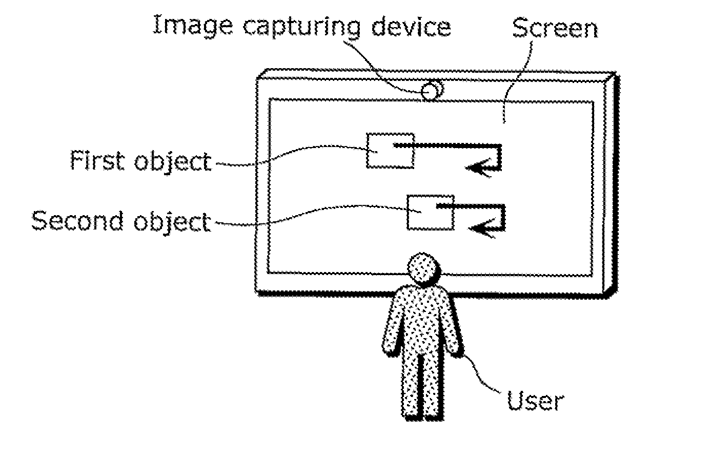
[0071]Generally, eye movement of a user tracks the movement of the object at which the user is gazing. Thus, there is a temporal synchronization structure between the movement of the object at which the user is gazing and the eye movement of the user. It is possible to determine the object at which the user is gazing by analyzing the synchronization structure. For the analysis of the synchronization structure, it is necessary to move or change an object so as to cause eye movement that can be easily detected even when an error in the detection of the gaze direction is large.

[0072]In the following description, a display event (event) refers to at least one of the characteristic movement and change of at least part of an object, which causes eye movement that can be easily detected even when an error in the detection of the gaze direction is large. Note that change of at least part of...


PUM


Abstract

The object at which a user is gazing Is accurately determined from among objects displayed on a screen. A gaze target determination device (10) includes: an event setting unit (13) which generates, for each object at different times, a display event which triggers a movement of the gaze direction of the user who is gazing at the object and which indicates a movement or a change of the object; a gaze trajectory calculation unit (12) which calculates a gaze trajectory based on the detected user's gaze direction; an eye movement event detection unit (14) which detects event detection time which is time at which the gaze direction moves according to the display event, based on the calculated gaze trajectory; a synchronization structure analysis unit (15) which calculates, for each object, time difference between the event detection time and event occurrence time; and a gaze target determination unit (16) which determines the object at which the user is gazing from among the objects, based on the calculated time difference.

Description

TECHNICAL FIELD[0001]The present invention relates to a gaze target determination device which determines the object at which a user is gazing from among a plurality of objects displayed on a screen.BACKGROUND ART[0002]Generally, the position of gaze on a screen obtained from eye gaze direction of a user is compared with a position of an object displayed on the screen to determine the object at which the user is gazing (hereinafter, may be simply referred to as a “gaze target”). Examples of a method for detecting an eye gaze direction include a corneal reflex method that estimates the gaze direction utilizing the positions of a pupil and a light source image (Purkinje image) that is a reflection, on a cornea, of near-infrared light irradiated on an eye by a light emitting diode (LED). Another example of a method for detecting an eye gaze is a method that detects the gaze direction utilizing a three-dimensional eye model or the like based on a user image captured by a video camera, a...

Claims


Application Information

Patent Timeline
Patent Type & Authority Applications(United States)
IPC IPC(8): G09G5/00G06F17/21
CPCA61B3/113G06V40/193
Inventor SAKATA, KOTAROMAEDA, SHIGENORIYONETANI, RYOKAWASHIMA, HIROAKIHIRAYAMA, TAKATSUGUMATSUYAMA, TAKASHI
Owner PANASONIC INTELLECTUAL PROPERTY CORP OF AMERICA
Why Eureka
Try Eureka