Thermal head and printer

Inactive Publication Date: 2011-06-16
SEIKO INSTR INC
View PDF3 Cites 0 Cited by
  • Summary
  • Abstract
  • Description
  • Claims
  • Application Information

AI Technical Summary

Benefits of technology

[0023]Because the printer includes the above-mentioned thermal head, while maintaining the printing quality, the thermal efficiency of the thermal head may be increased to reduce an amount of energy required for printing. Therefore, printing on thermal paper may be performed with low power to prolong battery duration. Besides, a failure due to th

Problems solved by technology

However, if the thickness of the intermediate layer is too large, the heat dissipation effect toward the support substrate is significantly reduced to raise a temperature of the upper substrate excessively, resulting in low printing quality.
However, in the case of forming the intermediate layer by screen printing using a glass paste, there is an inconvenience that a glass thickness obtained after baking ma

Method used


Image

  • Thermal head and printer
  • Thermal head and printer
  • Thermal head and printer

Examples


Example

First Modified Example

[0069]A first modified example of the thermal head 1 according to this embodiment is described below.

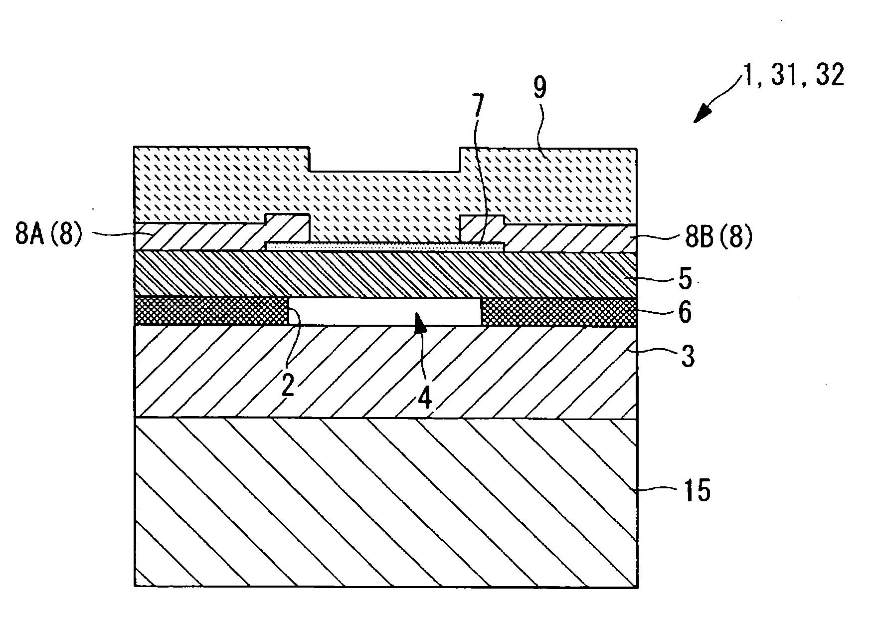
[0070]A thermal head 31 according to this modified example is different from the thermal head 1 according to the above-mentioned embodiment in that the intermediate layer 6 is formed of at least one laminated green sheet. The description common to the thermal head 1 according to the above-mentioned embodiment is omitted below, and hence the following description is mainly directed to the difference.

[0071]A green sheet is what is obtained by mixing an organic binder and a solvent into glass powders, which are ground into a constant micro grain diameter, and by sheeting the resultant slurry by a film-forming apparatus. Here, in order to adjust the characteristics of glass, a green sheet is manufactured in the following way. The above-mentioned low-melting glass powders and other glass powders are mixed at a predetermined ratio, and an organic binder and the like a...

Example

Second Modified Example

[0076]A second modified example of the thermal head 1 according to this embodiment is described below.

[0077]A thermal head 32 according to this modified example is different from the thermal head 1 according to the above-mentioned embodiment in that the intermediate layer 6 is formed using a thin plate glass. The description common to the thermal head 1 according to the above-mentioned embodiment is omitted below, and hence the following description is mainly directed to the difference.

[0078]Used herein as the thin plate glass is one obtained by processing a low-melting glass plate to have a desired thickness under an appropriate wet etching condition. Alternatively, low-melting glass powders and other glass powders are mixed at a predetermined ratio and processed into a plate shape, and thereafter thinning may be performed by wet etching, mechanical polishing, rolling accompanied by heating, or the like.

[0079]A method of forming the concave portion 2 in the i...


PUM


Abstract

Provided is a thermal head including an intermediate layer between a support substrate and an upper substrate, which is capable of suppressing heat dissipation toward the support substrate while maintaining printing quality. Employed is a thermal head (1) including: an upper substrate (5); a support substrate (3) bonded in a stacked state on one surface side of the upper substrate (5); a heating resistor (7) provided on another surface side of the upper substrate (5); and an intermediate layer (6) including a concave portion that forms a cavity portion (4) in a region corresponding to the heating resistor (7), the intermediate layer (6) being provided between the upper substrate (5) and the support substrate (3), in which the intermediate layer (6) is formed of a plate-shaped glass material having a lower melting point than melting points of the upper substrate (5) and the support substrate (3).

Description

BACKGROUND OF THE INVENTION[0001]1. Field of the Invention[0002]The present invention relates to a thermal head and a printer.[0003]2. Description of the Related Art[0004]There has been conventionally known a thermal head for use in printers, in which an intermediate layer is provided between a support substrate and an upper substrate and the intermediate layer has a cavity portion formed therein in a region corresponding to heating resistors (see, for example, Japanese Patent Application Laid-open No. 2007-83532).[0005]In the thermal head disclosed in Japanese Patent Application Laid-open No. 2007-83532, the cavity portion formed in the intermediate layer functions as a heat-insulating layer of low thermal conductivity to reduce an amount of heat transferring from the heating resistors toward the support substrate, to thereby increase thermal efficiency and reduce power consumption.[0006]In the thermal head disclosed in Japanese Patent Application Laid-open No. 2007-83532, when the...

Claims


Application Information

Patent Timeline
IPC IPC(8): B41J2/335
CPCB41J2/33585B41J2/3358
Inventor SANBONGI, NORIMITSUMOROOKA, TOSHIMITSUKOROISHI, KEITAROSHOJI, NORIYOSHI
Owner SEIKO INSTR INC
Why Eureka
Try Eureka