Cryogenic liquefying/refrigerating method and system

Inactive Publication Date: 2007-11-01
MAYEKAWA MFG CO LTD
View PDF5 Cites 10 Cited by
  • Summary
  • Abstract
  • Description
  • Claims
  • Application Information

AI Technical Summary

Benefits of technology

[0039] According to the method of the invention, gas-to-be-liquefied discharged from a compressor and precooled is further cooled by a chemical refrigerating machine which utilizes waste heat generated in the compressor, so the gas is further reduced in temperature before it is introduced to a multiple-stage heat exchanger in a cold box. Therefore, temperature of low temperature low pressure gas returned to the compressor is reduced and specific volume of gas-to-be-liquefied sucked in by the compressor is reduced, and power input to the compressor can be reduced. Further, as waste heat generated in the compressor can be effectively utilized, thermal efficiency of total system can be markedly increased as compared with the cryogenic liquefying/regenerating system of prior art.
[0040] By further cooling the gas-to-be-liquefied cooled by the chemical refrigerating machine by a vapor compression refrigerating machine before the gas is introduced to the multiple-stage heat exchanger, temperature of the gas-to-be-liquefied supplied to the heat exchanger can be further lowered, and power input to the compressor can be further reduced.
[0041] According to the system of the invention, temperature of gas-to-be-liquefied introduced to the first stage of a multiple-stage heat exchanger in a cold box is reduced by providing a chemical refrigerating machine so that the gas is cooled in the downstream zone from an aftercooler and before introduced to the first stage of the heat exchanger. Therefore, temperature of l

Problems solved by technology

Therefore, gas temperature sucked into the compressor can not be lowered without reducing the temperature of the high pressure gas introduced to the first stage of heat exchanger in the cold box.
Therefore, power input to the compr

Method used


Image

  • Cryogenic liquefying/refrigerating method and system
  • Cryogenic liquefying/refrigerating method and system
  • Cryogenic liquefying/refrigerating method and system

Examples


first embodiment

The First Embodiment

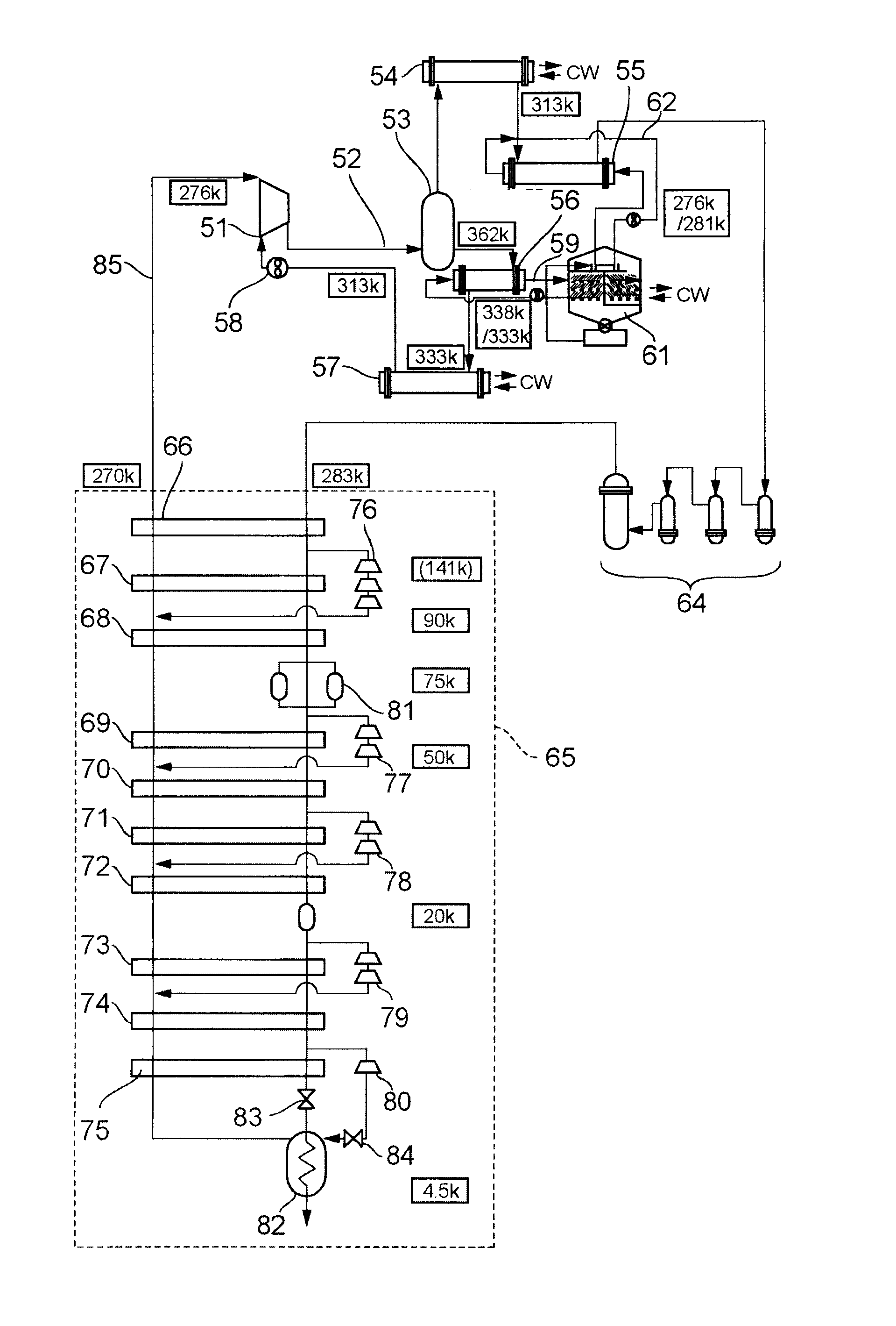
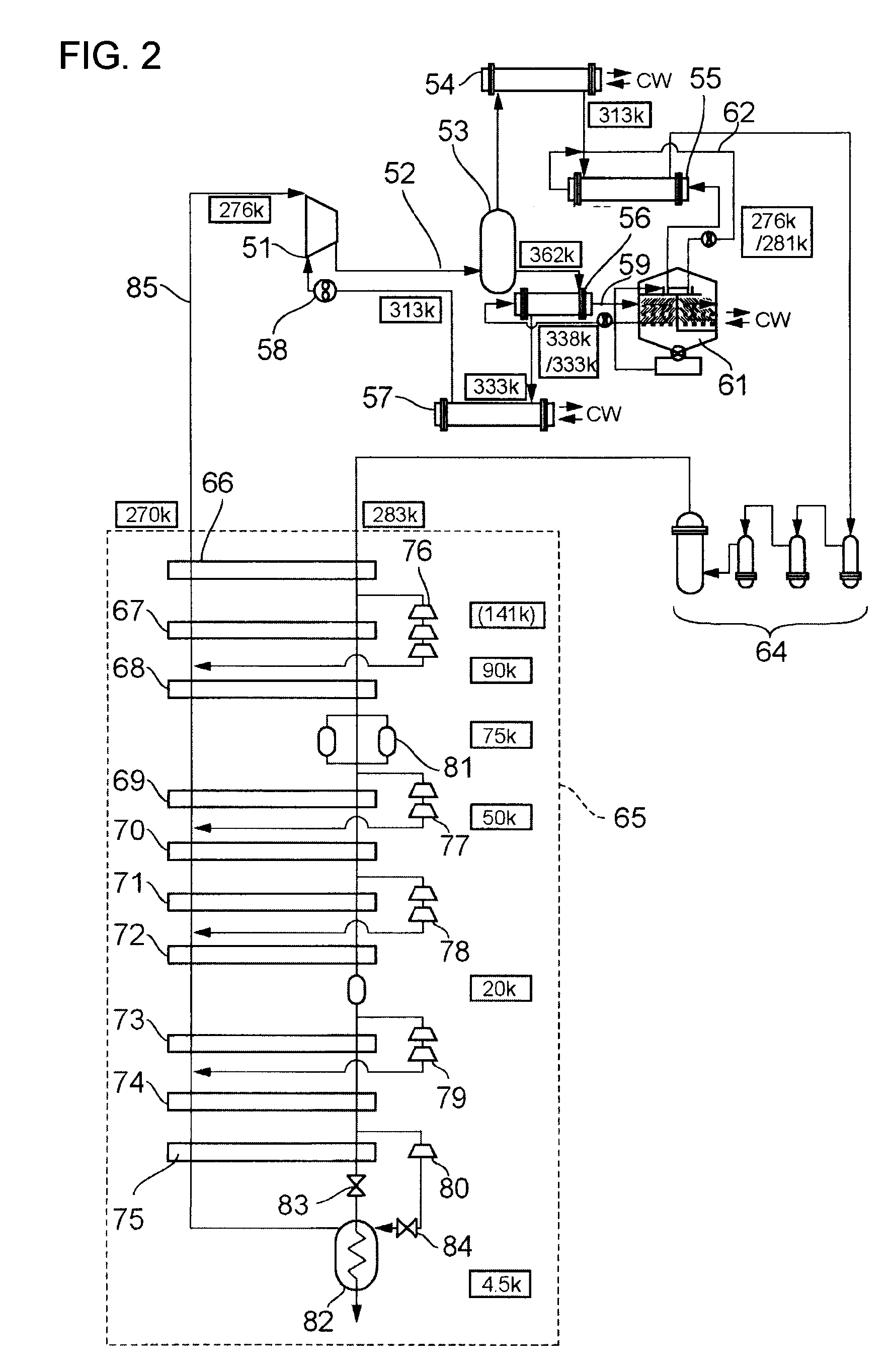
[0052]FIG. 2 is a schematic diagram of the first embodiment of the invention applied to a helium liquefying / refrigerating system. In the drawing, reference numeral 51 is a compressor, in a high pressure line 52 extending from the outlet thereof are provided an oil separator 53, a primary after cooler 54, a second after cooler 55 in this order. Lube oil of the compressor mixed in the high pressure gas discharged from the compressor 51 is separated in the oil separator 53, then the lube oil gives heat to hot water flowing through a hot water line 59 in a heat recovering device 56, then cooled in an oil cooler 57 and returned to the compressor 51 by means of an oil pump 58.

[0053] The high pressure gas got rid of lube oil in the oil separator 53 is cooled in a primary after cooler 54 and a secondary after cooler 55. The hot water heated by the lube oil and flowing in the hot water line 59 is introduced to an adsorption refrigerating machine 61 to be used as a heat s...

second embodiment

The Second Embodiment

[0061] Next, the second embodiment of the system according to the invention will be explained with reference to FIG. 3. The second embodiment is different from the first embodiment shown in FIG. 2 in that a heat exchanger 91 is added in the downstream side of the precision oil separator 64 in the high pressure line 52 and further an ammonia refrigerating machine 92 as a vapor compression refrigerating machine for supplying low temperature refrigerant to the heat exchanger 91 and a branch line 93 are added, other configuration is the same as that of the first embodiment. In FIG. 3, numerical values surrounded by quadrangles indicate temperature at each process.

[0062] In the second embodiment, the high pressure gas which was precooled in the secondary aftercooler 55 and passed through the precision oil separator 64 is further cooled in the heat exchanger 91 by the refrigerant supplied from the ammonia refrigerating machine 92. A portion of the low temperature wat...

third embodiment

The Third Embodiment

[0067] Next, the third embodiment in a case the present invention is applied to a re-liquefying system of natural gas will be explained referring to FIG. 4. In the drawing, reference numeral 101 is a compressor. A primary aftercooler 103 and a secondary aftercooler 104 are provided in this order in a high pressure gas line 102. High pressure gas discharged from the compressor 101 is cooled by these aftercoolers. Reference numeral 105 is a chemical refrigerating machine such as an adsorption refrigerating machine or absorption refrigerating machine, by which cold water is produced utilizing waste heat such as friction loss heat that lube oil received during lubrication of the compressor 101 and retained in the lube oil, in the same way as is by the adsorption refrigerating machine in the first and second embodiment. Said cold water is supplied via a circulation line 106 to the secondary aftercooler 104 as a cold source.

[0068] Reference numeral 107 is a first stag...


PUM


Abstract

Cryogenic liquefying/refrigerating method and system, wherein temperature of gas-to-be-liquefied at the inlet of the compressor for compressing the gas is reduced by cooling the gas discharged from the compressor using a high-efficiency chemical refrigerating machine and vapor compression refrigerating machine before the gas is introduced to a multiple stage heat exchanger thereby reducing power input to the compressor and improving liquefying/refrigerating efficiency. Gas-to-be-liquefied compressed by a compressor is cooled by aftercooler, and further cooled by an adsorption refrigerating machine which utilizes waste heat generated in the compressor and by an ammonia refrigerating machine 40, then the high pressure gas is introduced to a multiple-stage heat exchanger where it is cooled by low pressure low temperature gas separated from a mixture of liquid and gas generated by adiabatically expanding the high pressure gas through an expansion valve 30 and returning to the compressor, and a portion of the high pressure gas is expanded adiabatically by expansion turbines in mid-course of flowing of the high pressure gas through the stages of the heat exchanger to be joined with the low pressure low temperature gas returning to the compressor.

Description

CROSS REFERENCE TO RELATED APPLICATIONS [0001] This is a continuation of International Application PCT / JP05 / 03001 (published as WO 2006 / 051622) having an international filing date of 24 Feb. 2005, which claims, priority to JP2004-330160 filed on 15 Nov. 2004. The disclosures of the priority applications are incorporated herein by reference. TECHNICAL FIELD [0002] This invention relates to a method and system for effectively reducing driving power of a compressor and minimize total power consumption for operating a cryogenic liquefying / refrigerating system such as a helium liquefying / refrigerating system and natural gas re-liquefying system, by effectively utilizing waste heat generated in the compressor and sensible heat of gas discharged from the compressor, such utilization being not performed in the past, by a chemical refrigerating machine and vapor compression refrigerating machine for producing cold medium for precooling the gas discharged from the compressor before the gas is...

Claims


Application Information

Patent Timeline
IPC IPC(8): F25J1/00
CPCF25B9/06F25J1/0297F25J1/0007F25J1/0025F25J1/0037F25J1/004F25J1/0045F25J1/0208F25J1/0227F25J1/0242F25J1/0276F25J2220/62F25J2230/08F25J2230/60F25J2270/06F25J2270/906F25J2270/912F25B25/00F25J1/005F25J1/0052F25J1/0065F25J2230/30F25J1/0292F25J1/0202F25B9/00
Inventor INO, NOBUMIKISHI, TAKAYUKINISHIO, TOSHIOMACHIDA, AKITOSEKIYA, YOSHIMITSUKOHAMA, MASAMINOGUCHI, MASATO
Owner MAYEKAWA MFG CO LTD
Why Eureka
Try Eureka