Optical anemometric probe with two measurement axes

an anemometer and optical anemometer technology, applied in the field of optical anemometer, can solve the problems of complex solutions and high cost, and achieve the effect of reducing these drawbacks

Inactive Publication Date: 2011-06-16
THALES SA
View PDF12 Cites 30 Cited by
  • Summary
  • Abstract
  • Description
  • Claims
  • Application Information

AI Technical Summary

Benefits of technology

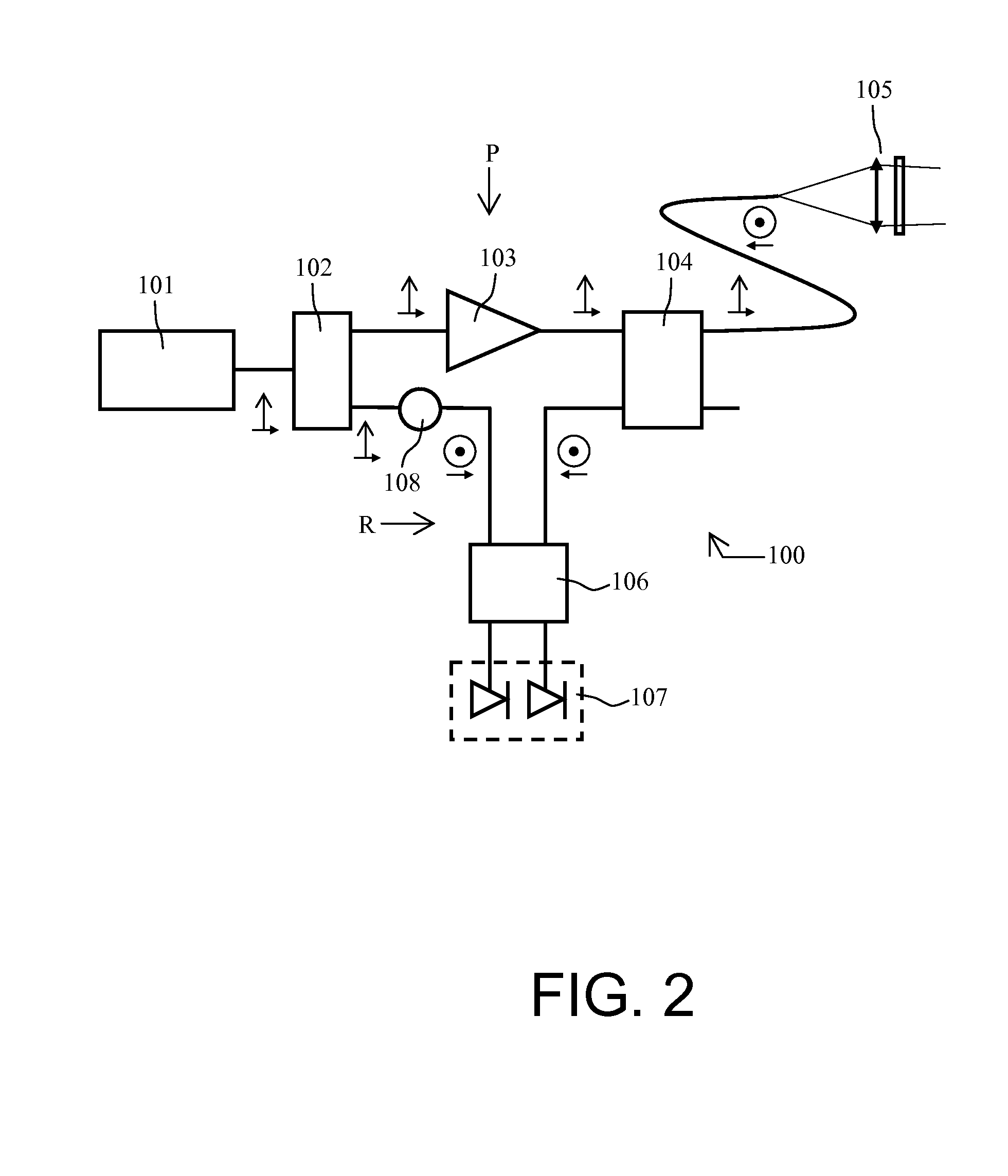
[0028]The device according to the invention alleviates these drawbacks. The idea includes minimally modifying the optical architecture to to offer more angles of view, that is to say measurement axes, without multiplying the number of sources, of means of amplification, of detection or of processing of the signal. As was seen on the device of FIG. 2, a single polarization of the light is used on emission and on reception. The device according to the invention uses two mutually perpendicular light polarization axes. Two luminous fluxes coming from the same source are thus emitted on two differently oriented optical heads, both fluxes being polarized linearly but their polarization planes being perpendicular. The detection and the analysis of the signals backscattered by these two optical heads can be done very simply. Two measurement axes are thus created without considerably overburdening the optical architecture.

Problems solved by technology

These solutions are necessarily complex and expensive.

Method used


Image

  • Optical anemometric probe with two measurement axes
  • Optical anemometric probe with two measurement axes
  • Optical anemometric probe with two measurement axes

Examples


Embodiment Construction

[0051]By way of example, FIG. 3 represents a first optical architecture of a LiDAR “with two optical heads” according to the invention. It essentially comprises a laser source 201 emitting a linearly polarized primary light beam, an optical block 220 and an optical measurement pathway 230 which are detailed hereinbelow.

[0052]The laser source 201 provides a linearly polarized primary reference wave. In FIG. 3, the direction of polarization of this wave is in the plane of the sheet.

[0053]The optical block 220 includes:[0054]Optical means 210 of rotation of the polarization arranged at the output of the laser source, these optical means of rotation of the polarization making it possible to rotate the plane of polarization of the primary light beam by a known angle;[0055]A splitter device 202 separating the polarized reference wave provided by this source 201 into two secondary beams, the first secondary beam passing through an optical reference pathway, the second secondary beam passin...


PUM

PropertyMeasurementUnit
optical anemometric probeaaaaaaaaaa
relative altitudeaaaaaaaaaa
speedaaaaaaaaaa

Abstract

An optical anemometric probe includes a laser source emitting a linearly polarized primary light beam and an optical block having splitting means for separating the primary beam, an optical reference pathway, an optical emission pathway and an optical measurement pathway. The optical block includes optical means of rotation of the polarization arranged at the output of the laser source and before the splitting means. The optical emission pathway has an optical circulator, a first optical emission/reception head illuminating a first measurement zone, and a second optical emission/reception head illuminating a second measurement zone. The optical circulator has four ports, e.g., a first input port, a second and a third input/ouput port linked respectively to the first optical head and to the second optical head, and a fourth port linked to the optical measurement pathway.

Description

CROSS-REFERENCE TO RELATED APPLICATION[0001]This application claims priority to foreign French patent application No. FR 09 06002, filed on Dec. 11, 2009, the disclosure of which is incorporated by reference in its entirety.FIELD OF THE INVENTION[0002]The field of the invention is that of optical anemometry and in particular optical anemometry on board aircraft.BACKGROUND OF THE INVENTION[0003]To pilot an aircraft, it is necessary to know at least its relative altitude, its speed with respect to the ambient air and its angle of attack. These various data may be measured locally, in the near field, in the vicinity of the skin of the aircraft or in the far field, away from the aerodynamic field disturbed by the craft. The near-field data are obtained conventionally by measuring a certain number of aerodynamic parameters such as the static pressure allowing determination of the altitude, the total pressure allowing determination of the relative speed, the local angle of attack and the ...

Claims


Application Information

Patent Timeline
Patent Type & Authority Applications(United States)
IPC IPC(8): G01N21/00G01S17/87
CPCG01P5/16G01P5/26G01P13/025G01S17/87G01S7/499G01S17/58G01S7/4818
Inventor SCHLOTTERBECK, JEAN-PIERRERONDEAU, PHILIPPE
Owner THALES SA
Why Eureka
Try Eureka