
Method for monitoring a component in a hydraulic circuit, monitoring device and fluid turbine

a monitoring device and fluid turbine technology, applied in the direction of machines/engines, sustainable manufacturing/processing, engine starters, etc., can solve the problems of difficult detection of fluid performance of pumps or leakages in systems not supervised, difficult detection of whether a component in the hydraulic circuit of a wind turbine is properly working, and component in the hydraulic circuit may have a leakag

Inactive Publication Date: 2011-06-16
GENERAL ELECTRIC CO
View PDF2 Cites 56 Cited by
  • Summary
  • Abstract
  • Description
  • Claims
  • Application Information

AI Technical Summary

Problems solved by technology

For example, the volumetric performance of a pump or leakages are difficult to detect in systems not supervised by humans.
Further, it may be difficult to detect whether a component in the hydraulic circuit of a wind turbine is properly working.
For example, a component in the hydraulic circuit may have a leakage.
In conventional hydraulic systems it is hard to measure, for example, the exact swash plate position in a radial piston hydraulic motor as the position is not necessarily measured in the first place and in the event it is measured it is not cheap to get the accuracy required.
For example, volumetric losses may increase due to wear of hydrostatic transmissions.

Method used


Image

  • Method for monitoring a component in a hydraulic circuit, monitoring device and fluid turbine
  • Method for monitoring a component in a hydraulic circuit, monitoring device and fluid turbine
  • Method for monitoring a component in a hydraulic circuit, monitoring device and fluid turbine

Examples


Embodiment Construction

[0016]Reference will now be made in detail to the various embodiments, one or more examples of which are illustrated in each figure. Each example is provided by way of explanation and is not meant as a limitation. For example, features illustrated or described as part of one embodiment can be used on or in conjunction with other embodiments to yield yet further embodiments. It is intended that the present disclosure includes such modifications and variations.

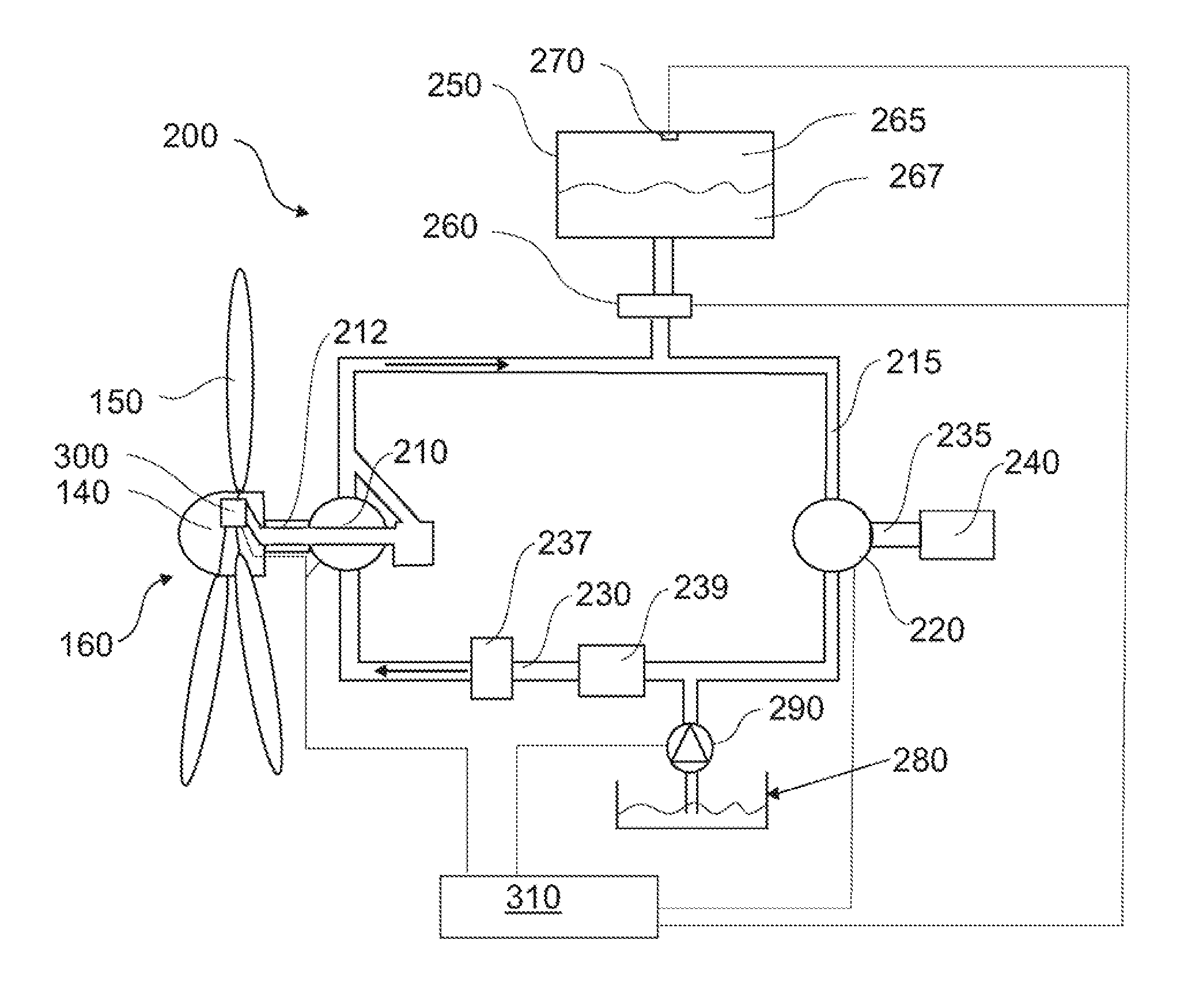
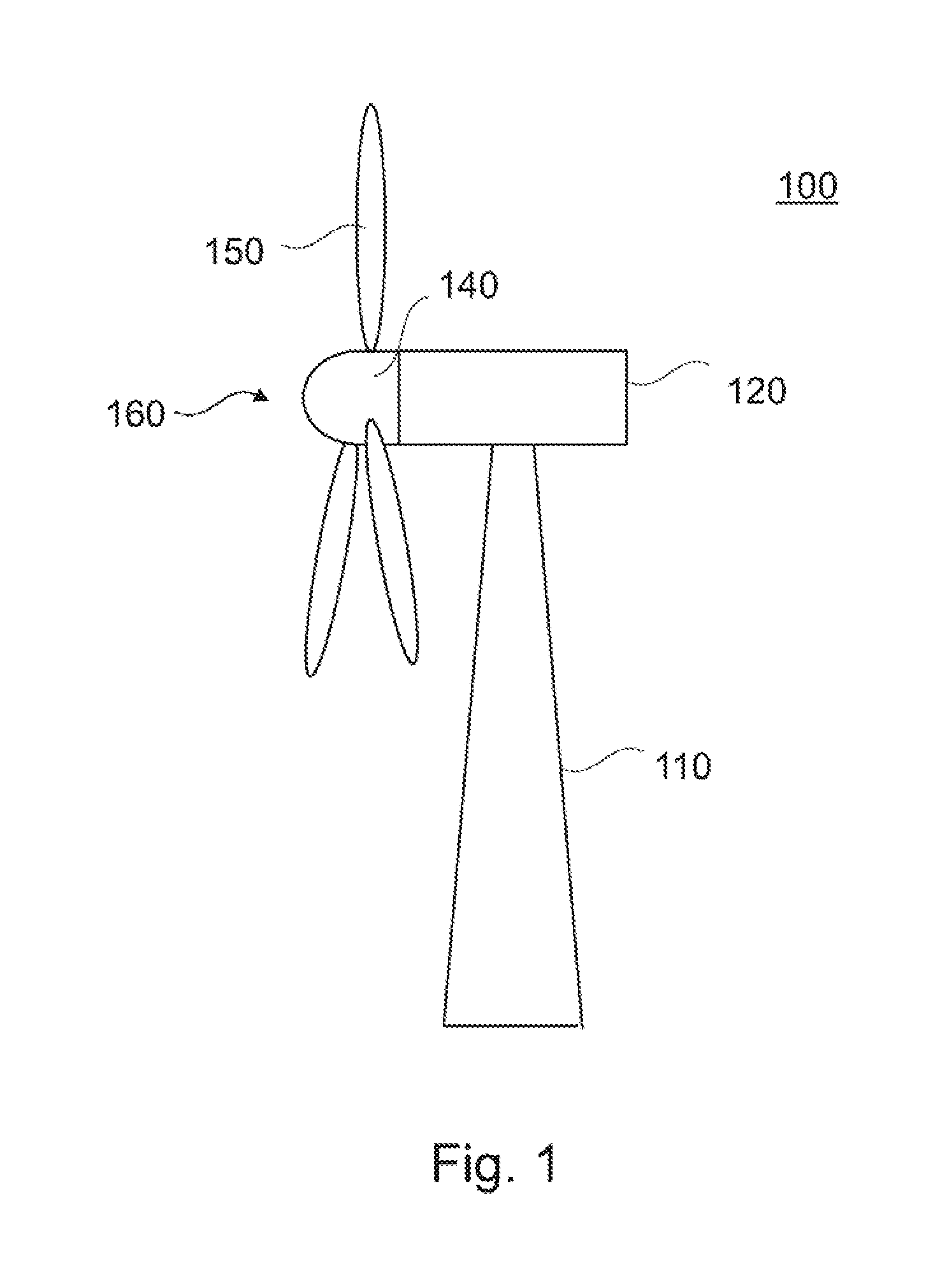
[0017]FIG. 1 shows a wind turbine 100. The wind turbine 100 includes a tower 110 on which a nacelle 120 is mounted. The nacelle 120 is rotatable about a vertical axis of the tower 110. Within the nacelle 120 a generator (not shown) for transforming rotational power into electrical power is placed. The generator is connected to a hub 130 that is rotatable about a horizontal axis. Three rotor blades 140 are connected to the hub 130. The rotor blades 140 and the hub 130 together form a wind rotor of the wind turbine 100. The wind t...


PUM


Abstract

The disclosure concerns a method for monitoring at least one component to be monitored in a hydraulic circuit filled with a working fluid, the hydraulic circuit comprises at least one pump for circulating the working fluid, wherein the method comprises:—changing an operational state of at least one first component in the hydraulic circuit such that a working point of the at least one component to be monitored changes to a predetermined working point;—performing at least one measurement for monitoring the at least one component to be monitored. Further, the disclosure concerns a monitoring device for monitoring at least one component to be monitored in a hydraulic circuit being filled with a working fluid. Further, the disclosure concerns a fluid turbine comprising at least one fluid rotor, wherein the fluid rotor is adapted to convert kinetic power of a fluid into a rotation, the fluid turbine further comprising a hydraulic circuit filled with a working fluid.

Description

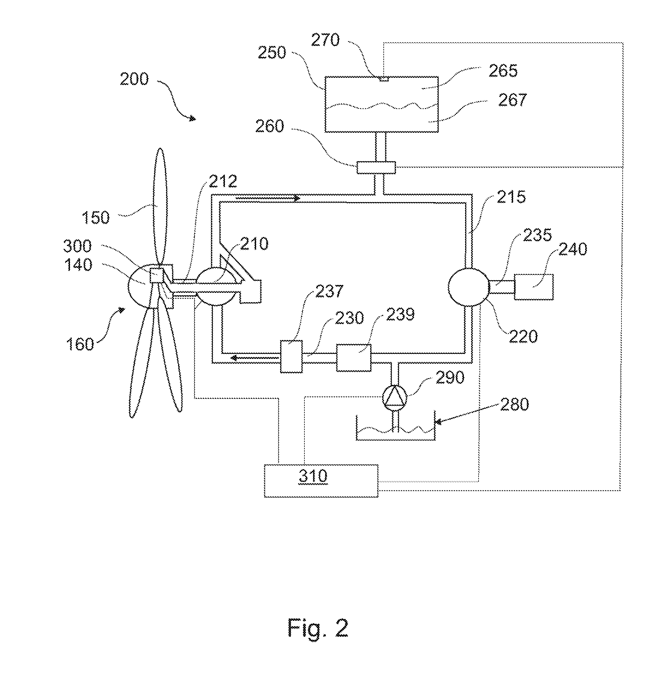
BACKGROUND OF THE INVENTION[0001]The present disclosure relates to a method for monitoring at least one component in a hydraulic circuit. Further, the present disclosure relates to a monitoring device that is provided for monitoring at least one component in a hydraulic circuit. According to another aspect, the present disclosure relates to a fluid turbine comprising at least one fluid rotor.[0002]Wind turbines may include a mechanical gear box between the wind rotor and the generator of the wind turbine. In further embodiments, a hydraulic transmission between the wind rotor and the generator may be used. In such wind turbines which have a hydraulic transmission between the rotation of the wind rotor and the rotor of the generator there is a transmission ratio which may be arbitrarily chosen. Typically, in traditional hydraulic equipment, the flow rate is controlled but often not quantified in the control system. For example, the volumetric performance of a pump or leakages are dif...

Claims


Application Information

Patent Timeline
IPC IPC(8): F03B15/00F15B13/00
CPCF03D9/001Y02E60/17Y02E10/72F15B19/005F03D9/28Y02E60/16Y02P80/10Y10T137/0318Y10T137/8158F03D9/17F03D9/25F03D17/00
Inventor NIES, JACOB JOHANNES
Owner GENERAL ELECTRIC CO
Learn More