Turbine Blade Damping Device with Controlled Loading

a technology of vibration damping and turbine blades, which is applied in the direction of liquid fuel engines, vessel construction, marine propulsion, etc., can solve the problems of snubbing surfaces, increasing the volume of flow through industrial turbine engines, and increasing the operating conditions (e.g., operating temperature and pressure)

Inactive Publication Date: 2011-06-16
SIEMENS ENERGY INC
View PDF12 Cites 17 Cited by
  • Summary
  • Abstract
  • Description
  • Claims
  • Application Information

AI Technical Summary

Benefits of technology

[0011]A midway point is defined between the first and second blades and a radial thickness of the snubber element may decrease extending from each of the blades to the midway point.

Problems solved by technology

As the capacity of electric power plants increases, the volume of flow through industrial turbine engines has increased more and more and the operating conditions (e.g., operating temperature and pressure) have become increasingly severe.
However, when the blades rotate at full load and untwist under the effect of the centrifugal forces, snubber surfaces on adjacent blades come in contact with each other.
A disadvantage of snubber damping is that on large diameter blades it is often difficult to achieve the desired contact forces produced between snubbers as a result of the centrifugal untwisting of the blades.
In addition, the large mechanical load associated with large diameter blades typically necessitates larger snubber structures for mechanical stability to avoid outward bending of the snubber, resulting in increased aerodynamic losses and flow inefficiencies due to the flow restriction of larger snubbers positioned in the high velocity flow area through the part-span area.

Method used


Image

  • Turbine Blade Damping Device with Controlled Loading
  • Turbine Blade Damping Device with Controlled Loading
  • Turbine Blade Damping Device with Controlled Loading

Examples


Embodiment Construction

[0018]In the following detailed description of the preferred embodiment, reference is made to the accompanying drawings that form a part hereof, and in which is shown by way of illustration, and not by way of limitation, a specific preferred embodiment in which the invention may be practiced. It is to be understood that other embodiments may be utilized and that changes may be made without departing from the spirit and scope of the present invention.

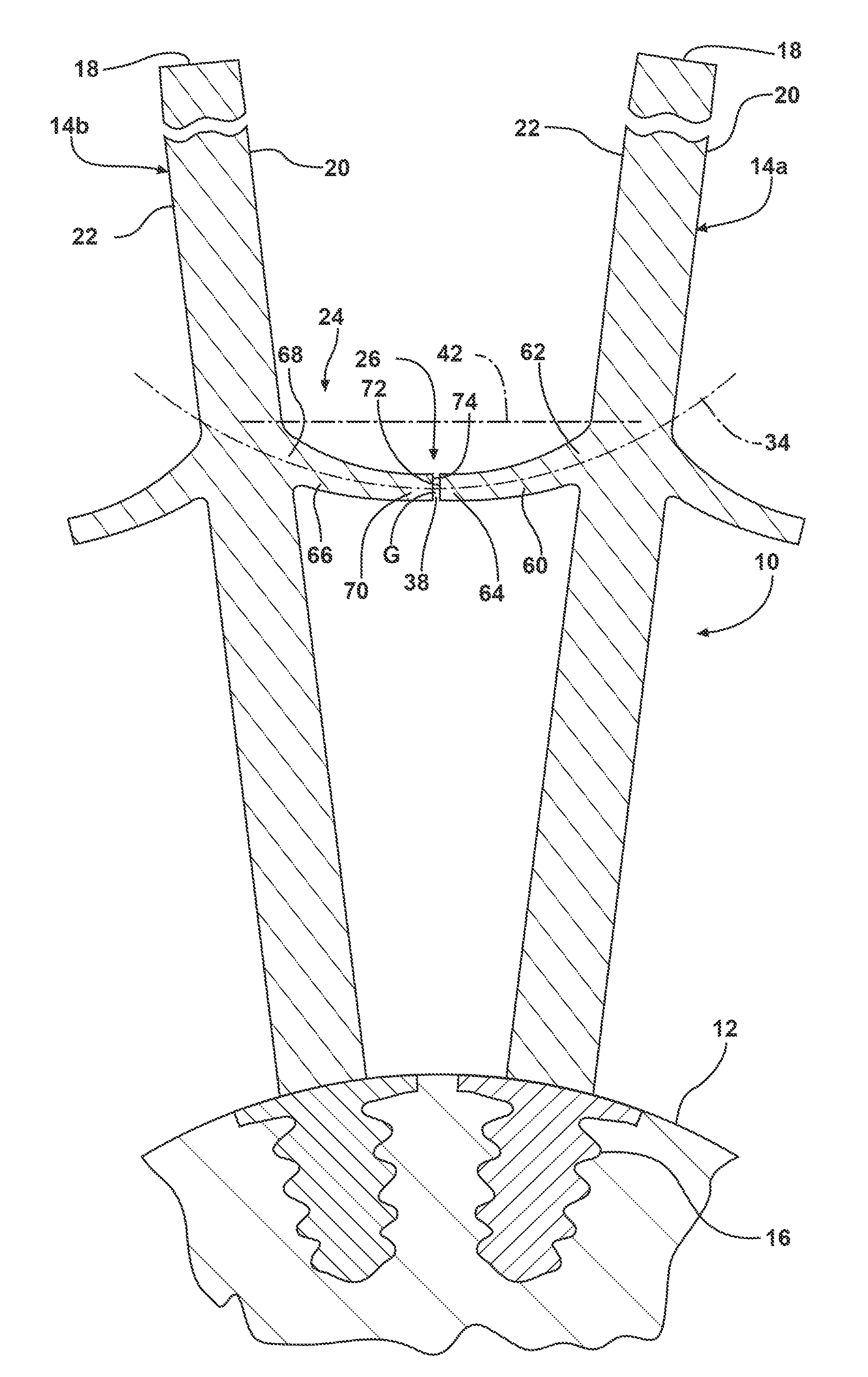
[0019]Referring to FIG. 1, a section of a rotor 10 is illustrated for use in a turbomachine (not shown), such as for use in a gas or steam turbine. The rotor 10 comprises a rotor disk 12 and a plurality of blades 14, illustrated herein as a first blade 14a and an adjacent second blade 14b. The blades 14 comprise radially elongated structures extending from a blade root 16, engaged with the rotor disk 12, to a blade tip 18. Each of the blades 14a, 14b includes a pressure side surface 20 and a suction side surface 22. The rotor 10 further ...


PUM


Abstract

A damping structure for a turbomachine rotor. The damping structure includes an elongated snubber element including a first snubber end rigidly attached to a first blade and extending toward an adjacent second blade, and an opposite second snubber end defining a first engagement surface positioned adjacent to a second engagement surface associated with the second blade. The snubber element has a centerline extending radially inwardly in a direction from the first blade toward the second blade along at least a portion of the snubber element between the first and second snubber ends. Rotational movement of the rotor effects relative movement between the first engagement surface and the second engagement surface to position the first engagement surface in frictional engagement with the second engagement surface with a predetermined damping force determined by a centrifugal force on the snubber element.

Description

CROSS-REFERENCE TO RELATED APPLICATION[0001]This application is related to and filed on even date with an application having attorney docket number 2009P15834US entitled, “TURBINE BLADE DAMPING DEVICE WITH CONTROLLED LOADING”, which is incorporated herein by reference in its entirety.FIELD OF THE INVENTION[0002]The present invention relates generally to vibration damping of turbine blades in a turbomachine and, more particularly, to a damping structure comprising a snubber providing a controlled damping force.BACKGROUND OF THE INVENTION[0003]A turbomachine, such as a steam or gas turbine is driven by a hot working gas flowing between rotor blades arranged along the circumference of a rotor so as to form an annular blade arrangement, and energy is transmitted from the hot working gas to a rotor shaft through the rotor blades. As the capacity of electric power plants increases, the volume of flow through industrial turbine engines has increased more and more and the operating conditio...

Claims


Application Information

Patent Timeline
Patent Type & Authority Applications(United States)
IPC IPC(8): F01D5/22
CPCF01D5/22F04D29/324F05D2250/712F05D2260/96F04D29/668F04D29/66
Inventor BEECK, ALEXANDER R.
Owner SIEMENS ENERGY INC
Why Eureka
Try Eureka