Air purification apparatus and method of forming the same

a technology of air purification apparatus and air purification efficiency, which is applied in the direction of lighting and heating apparatus, physical/chemical process catalysts, heating types, etc., can solve the problems of limited effectiveness of physical filtration approaches, inefficient approaches, and waste of light energy from porous substrates, so as to improve air purification efficiency and improve the surface area of substrates. , the effect of improving the coverage area

Active Publication Date: 2011-06-16
HONEYWELL INT INC
View PDF19 Cites 10 Cited by
  • Summary
  • Abstract
  • Description
  • Claims
  • Application Information

AI Technical Summary

Benefits of technology

[0014]The spacing interval between two adjacent plate substrates can be adjusted and the substrates configured in any shape. The number of plates employed depends on the transmittance of the plate in the corresponding activation wavelength range. The light source can also be located near the periphery of an inner plate substrate. The inner and outer surface of the substrates may be configured with a porous and / or a coarse structure with dimensions on the order of microns or nanometers to improve surface area of the substrates and the coverage area of the photocatalyst, thereby improving air purification efficiency.

Problems solved by technology

Such physical filtration approaches are limited in their effectiveness, because they do not remove smaller size contaminants such as biological contaminants and volatile organic compounds.
One of the problems associated with such a prior art approach stems from the fact that the limited area of the photocatalyst in the honeycomb-shaped structure is illuminated and activated by the lamp for air cleaning, which is an inefficient approach.
Therefore, only a portion of the light illuminating the porous substrate is employed to activate the photocatalyst and the light energy stemming from the porous substrate is typically wasted.

Method used


Image

  • Air purification apparatus and method of forming the same
  • Air purification apparatus and method of forming the same
  • Air purification apparatus and method of forming the same

Examples


Embodiment Construction

[0027]The particular values and configurations discussed in these non-limiting examples can be varied and are cited merely to illustrate at least one embodiment and are not intended to limit the scope thereof.

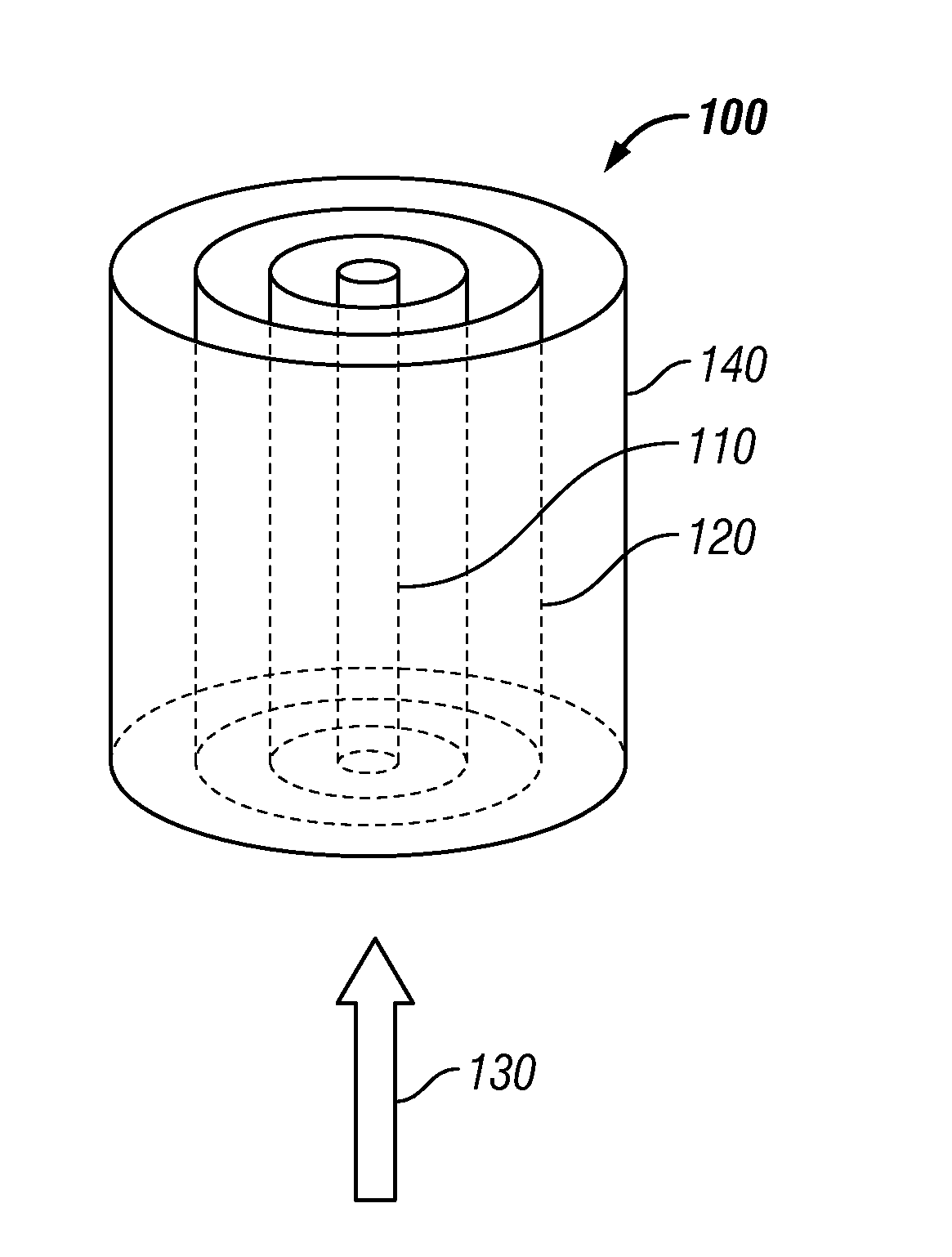
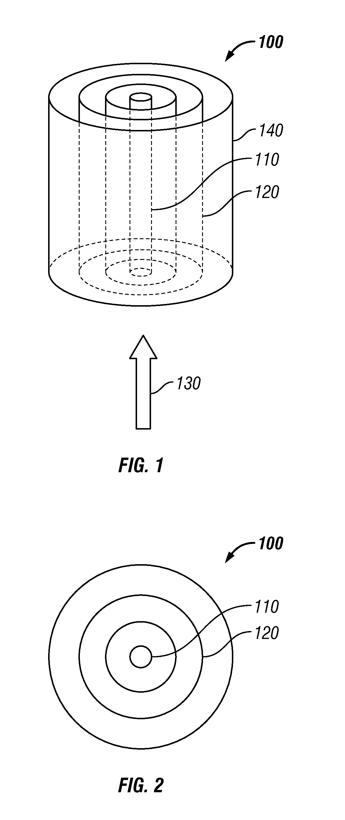
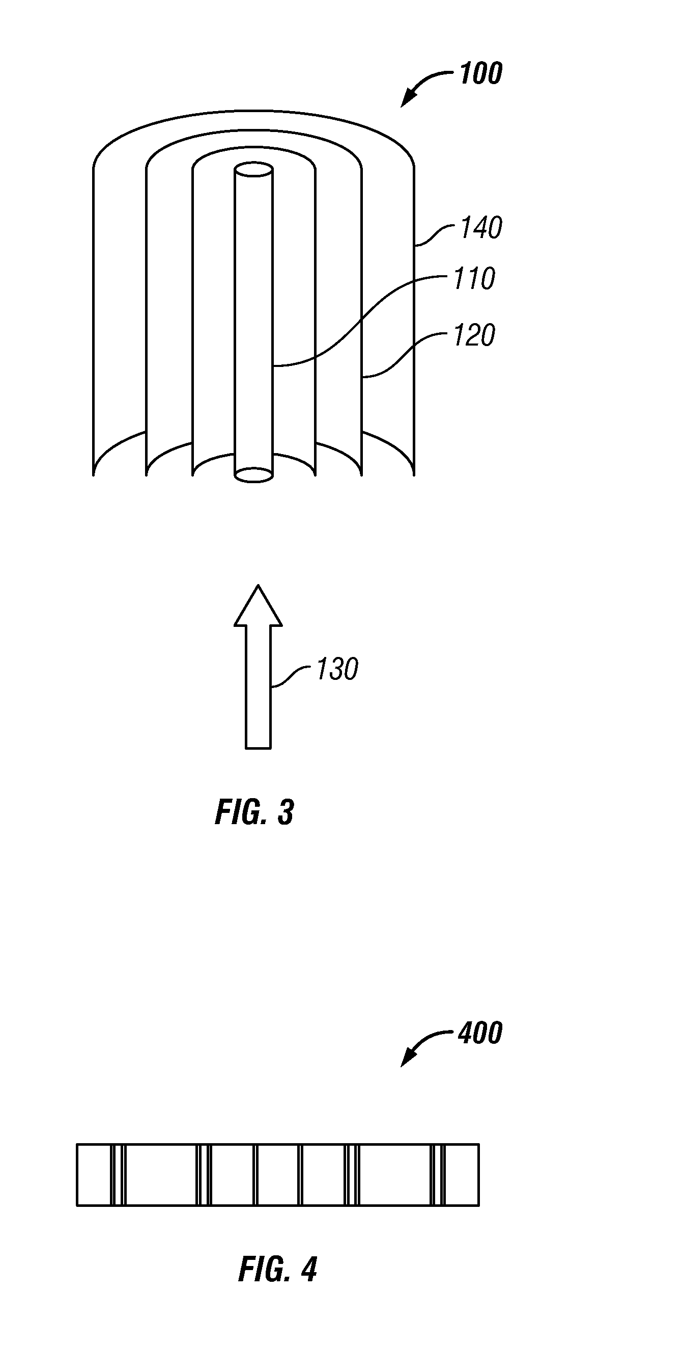
[0028]FIG. 1 illustrates a perspective view of an air purification apparatus 100, in accordance with the disclosed embodiments. The air purification apparatus 100 may be preferably installed in a wall of a room and located in an air passage through which the air of the room is circulated. The apparatus 100 purifies the air (e.g., treated fluid) passing through the passage. Further, the apparatus 100 can also be installed in association with an IAQ system to clean air by mechanically capturing airborne pollutants and smaller size contaminants, such as biological contaminants and volatile organic compounds.

[0029]The air purification apparatus 100 can be configured to include a light source 110 and one or more plate substrates 120. Each plate substrate 120 can be coated with a pho...


PUM

PropertyMeasurementUnit
sizeaaaaaaaaaa
sizeaaaaaaaaaa
transmittanceaaaaaaaaaa

Abstract

A photocatalytic air purification apparatus and method of fabricating the same. The apparatus may be configured to include a light source surrounded by one or more porous plate substrates. An inner and outer surface of each plate substrate may be coated with a photocatalyst material. The light source may be placed in a direction parallel to the direction of an air flow and in optical proximity to the plate substrates in order to activate the photocatalyst coating. The photocatalyst coating associated with the plate substrates may be activated by absorbing light with a wavelength shorter than a cut-off activation wavelength from the light source in order to capture and decompose organic components and airborne pollutants in the air by the activated photocatalyst.

Description

TECHNICAL FIELD[0001]Embodiments are generally related to air purification. Embodiments are also related to photocatalyst materials for use in air purification. Embodiments are additionally related to photocatalytic air purification.BACKGROUND OF THE INVENTION[0002]Air filtration is primarily employed in commercial and residential heating, ventilation, and air cooling systems for the removal of atmospheric dust, and other undesirable airborne matter. Air filters associated with an indoor air quality (IAQ) system, for example clean the air by mechanically capturing airborne pollutants such as dust, pet hair, dander, pollen, etc, which have a relatively large size of more than 10 um. Conventional electronic air cleaners remove particles in a size range between approximately 0.3 um to 10 um. Such physical filtration approaches are limited in their effectiveness, because they do not remove smaller size contaminants such as biological contaminants and volatile organic compounds.[0003]Pho...

Claims


Application Information

Patent Timeline
Patent Type & Authority Applications(United States)
IPC IPC(8): A61L9/00A61L9/20B01J37/34F24F3/16B23P17/00
CPCA61L2209/14Y10T29/49885A61L9/205
Inventor LIU, XUANBINWANG, LI
Owner HONEYWELL INT INC
Why Eureka
Try Eureka