Approach for variable pressure oil injection

a variable pressure oil and oil injection technology, applied in the direction of machines/engines, auxiliary lubrication, instruments, etc., can solve the problems of increased engine knock, reduced drivability, and degraded engine performance, and increase the amount of oil that is injected by the oil injector to accommodate different operating conditions

Active Publication Date: 2011-06-16
FORD GLOBAL TECH LLC
View PDF12 Cites 30 Cited by
  • Summary
  • Abstract
  • Description
  • Claims
  • Application Information

AI Technical Summary

Benefits of technology

Piston cooling jets or oil injectors may be implemented in an engine to provide engine cylinder cooling. In particular, each oil injector sprays oil onto an underside of a corresponding piston to create a cooling effect on the piston. Furthermore, the oil propagates from the underside of the piston to the surrounding walls of a corresponding engine cylinder as the piston reciproca

Problems solved by technology

However, the inventors have recognized several potential issues with such a configuration.
For example, since operation of the oil injector is merely based on the pressure setting of the check valve in the oil injector assembly, the amount of oil that is injected by the oil injector cannot be adjusted to accommodate different operating conditions.
In one example, if the check valve pressure level is set too high, then the

Method used


Image

  • Approach for variable pressure oil injection
  • Approach for variable pressure oil injection
  • Approach for variable pressure oil injection

Examples


Embodiment Construction

The subject matter of the present disclosure is now described by way of example and with reference to certain illustrated embodiments. It will be noted that figures included in this disclosure are schematic, and are identified as such. In the schematic figures, views of the illustrated embodiments are generally not drawn to scale; aspect ratios, feature size, and numbers of features may be purposely distorted to make selected features or relationships easier to see.

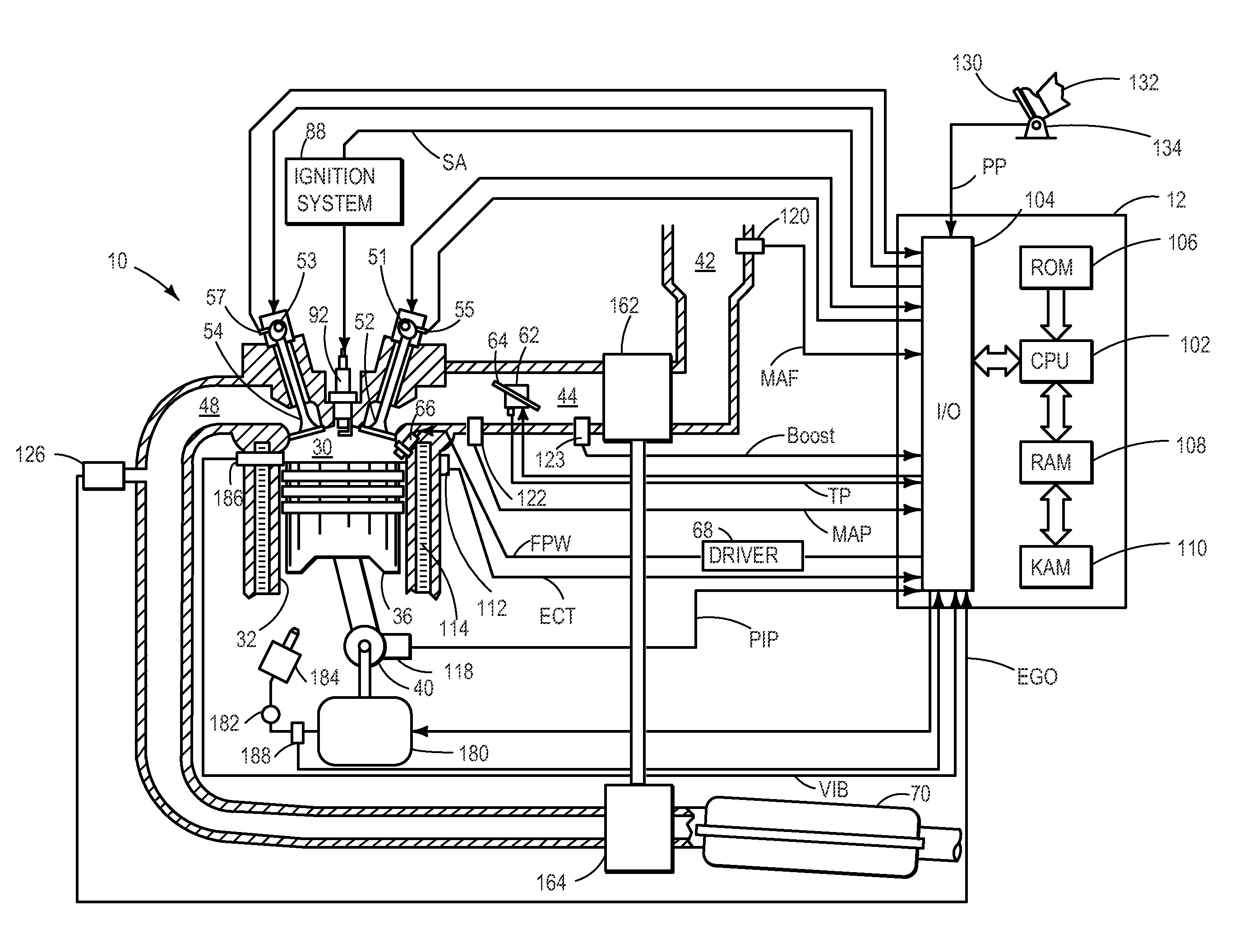
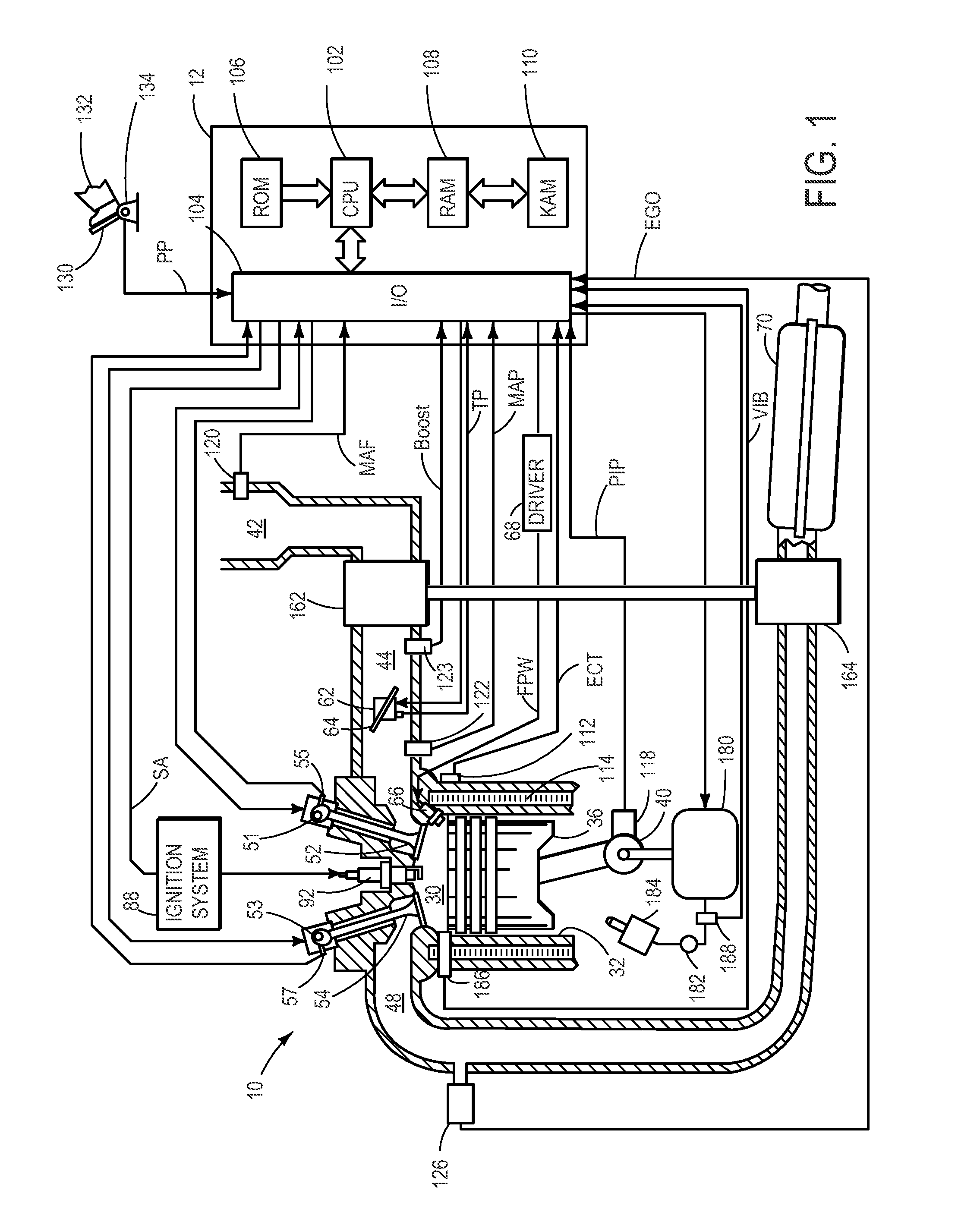
FIG. 1 is a schematic diagram showing one cylinder of multi-cylinder engine 10, which may be included in a propulsion system of an automobile. Engine 10 may be controlled at least partially by a control system including controller 12 and by input from a vehicle operator 132 via an input device 130. In this example, input device 130 includes an accelerator pedal and a pedal position sensor 134 for generating a proportional pedal position signal PP. Combustion chamber (i.e., cylinder) 30 of engine 10 may include combustion ...


PUM


Abstract

Varying oil injection by an oil injector onto a piston of an engine to accommodate different operating conditions.

Description

BACKGROUND AND SUMMARYPiston cooling jets or oil injectors may be implemented in an engine to provide engine cylinder cooling. In particular, each oil injector sprays oil onto an underside of a corresponding piston to create a cooling effect on the piston. Furthermore, the oil propagates from the underside of the piston to the surrounding walls of a corresponding engine cylinder as the piston reciprocates in the engine cylinder to provide a cooling effect to the combustion chamber. In one example, operation of an oil injector occurs when the oil pressure in the engine is sufficient to overcome a pressure level of a check valve in the oil injector assembly. As long as the oil pressure is greater than the pressure level of the check valve the injector injects oil onto the piston.However, the inventors have recognized several potential issues with such a configuration. For example, since operation of the oil injector is merely based on the pressure setting of the check valve in the oil...

Claims


Application Information

Patent Timeline
IPC IPC(8): F02D28/00F01M1/02
CPCF01M1/08F02D13/0226F02B37/00F02B3/06F02B2075/025Y02T10/12
Inventor BIDNER, DAVID KARLVANDERWEGE, BRAD ALANROLLINGER, JOHN ERICSMILEY, JOHN
Owner FORD GLOBAL TECH LLC
Why Eureka
Try Eureka