Conflict framework for guided structure synchronization

a technology of conflict framework and structure synchronization, applied in the field of structure synchronization, can solve the problems that the single synchronization of the mbom and the ebom is unlikely to be sufficient over the product lifecycle, and the design changes over time on the engineering side require resynchronization

Inactive Publication Date: 2011-06-16
SAP AG
View PDF6 Cites 44 Cited by
  • Summary
  • Abstract
  • Description
  • Claims
  • Application Information

AI Technical Summary

Problems solved by technology

Notably a single synchronization of the MBOM with the EBOM is unlikely to be sufficient over the product lifecycle.
Typically, design changes over time on the engineering side require resynchronization.

Method used


Image

  • Conflict framework for guided structure synchronization
  • Conflict framework for guided structure synchronization
  • Conflict framework for guided structure synchronization

Examples


Embodiment Construction

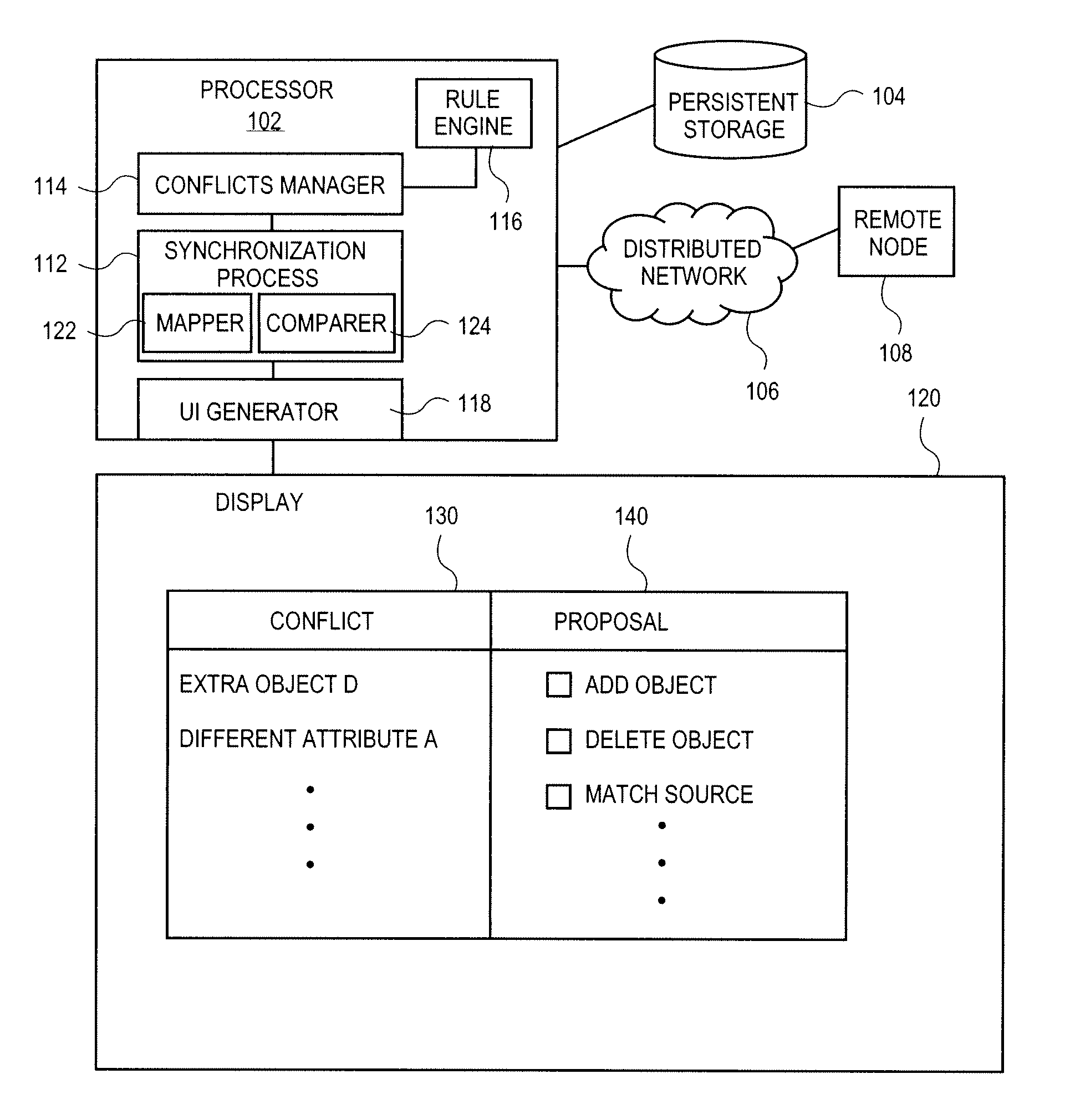
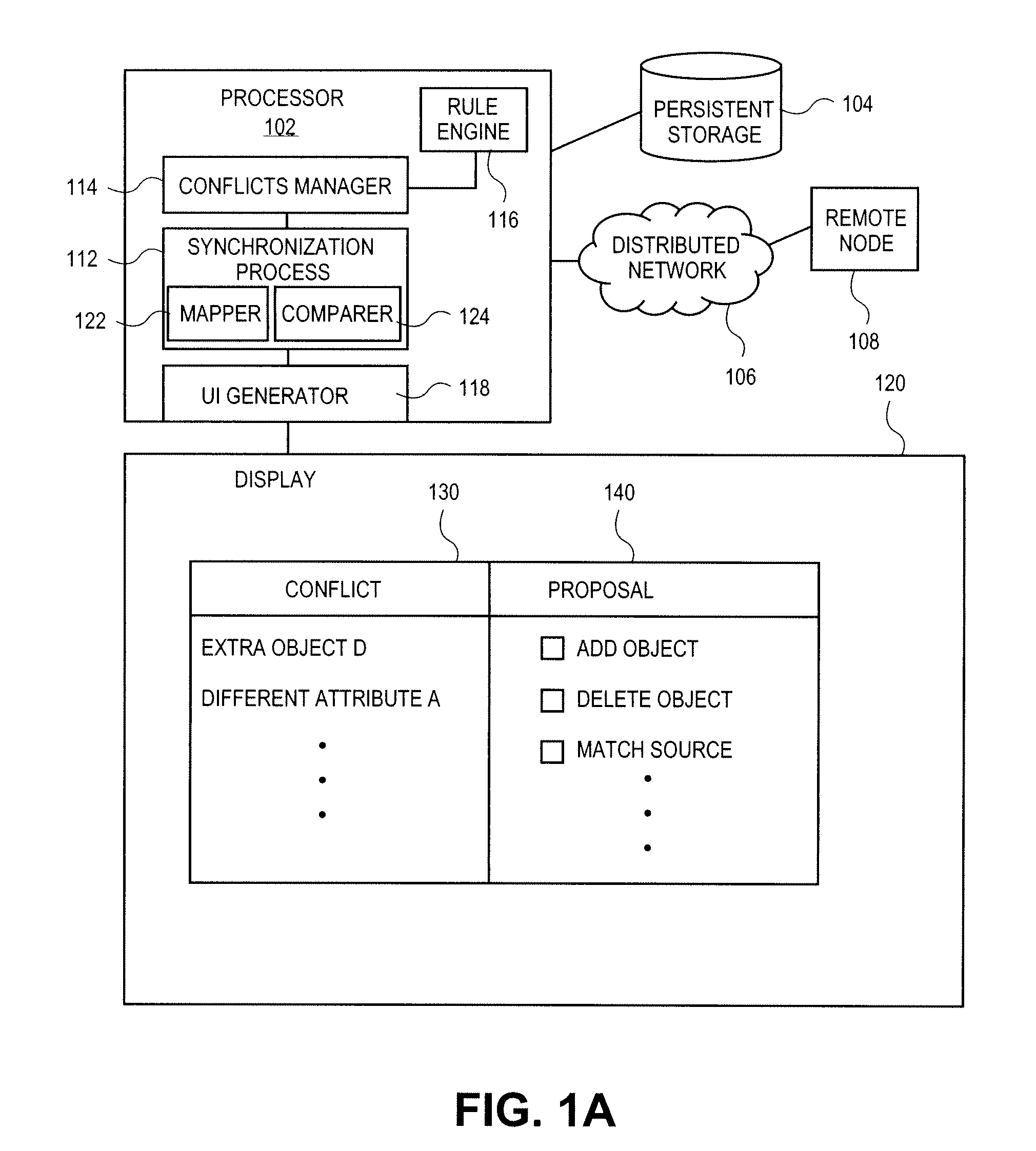
[0011]FIG. 1A is a block diagram of a system according to one embodiment of the invention. Processor 102 is coupled to a persistent storage 104 and a remote node 108 across a distributed network 106. Processor 102 is also coupled to display 120. Distributed network 106 may be a local area network (LAN) or a wide area network (WAN), such as the Internet.

[0012]A synchronization process 112 executes on processor 102 to ensure synchronization of source and target structures. Synchronization process 112 may be called by an application (not shown) executing on, for example, processor 102 or remote node 108 as the case may be. Synchronization process 112 includes a mapper 122 and a comparer 124, both of which set conflict checkpoints during the synchronization process. In some embodiments, the mapper 122 and comparer 124 may be enhanced with any of application specific, industry specific or customer specific mapping / comparing respectively.

[0013]FIG. 1B shows a schematic of a sample synchro...


PUM


Abstract

A system and method for handling conflicts during structure synchronization. Conflicts are identified as the structure moves through the synchronization process. An intermediate structure is generated on a format of a target structure. A proposal for resolution of the identified conflicts is created. The conflicts and proposed resolutions are presented to a user. Proposals accepted by the user are applied to the intermediate structure.

Description

BACKGROUND OF THE INVENTION[0001]1. Field[0002]Embodiments of the invention relate to structure synchronization. More specifically, embodiments of the invention relate to conflict handling during structure synchronization.[0003]2. Background[0004]As structures move along the value chain from product development through manufacturing ultimately to service, the structure often must change. For example, the “hand over to manufacturing,” which defines the transition from product structure from engineering to manufacturing necessitates a change in the structure. The role of product development (engineering) is to develop, validate, and document a product in accordance with certain requirements. Once that product has reached a certain level of maturity, the product data, typically including drawings, documents and master data for the materials and parts list, it is handed over to manufacturing. However, the design parts list from product development, typically referred to as an engineerin...

Claims


Application Information

Patent Timeline
Patent Type & Authority Applications(United States)
IPC IPC(8): G06F17/30G06F3/048
CPCG06F17/30348G06F17/30578G06F16/2308G06F16/273
Inventor HIMMELSBACH, GERHARDBOHNENGEL, TILMANRIEKEN, GREGOR
Owner SAP AG
Why Eureka
Try Eureka