Chemical reactor with nanometric superstructure

a nano-structure, chemical reactor technology, applied in nuclear engineering, metal/metal-oxide/metal-hydroxide catalysts, water/sewage treatment by ion exchange, etc., can solve the problems of inability to meet the requirements of all substrates, system requires additional steps, and the intermediate validation steps of the method are generally costly and difficult to predict, etc., to achieve excellent heat conductivity of the nano-structure, superior selectivity, and the effect of selective chemical reactions

Inactive Publication Date: 2011-05-26
CENT NAT DE LA RECHERCHE SCI +1
View PDF10 Cites 52 Cited by
  • Summary
  • Abstract
  • Description
  • Claims
  • Application Information

AI Technical Summary

Benefits of technology

[0131]A first advantage, the selectivity of the chemical reactions, has already been mentioned: firstly, the lack of ink-bottled pores gives rise to superior selectivity, secondly, the excellent heat conductivity of the nanometric superstructure to the macroscopic host structure prevents the formation of hot spots, which decrease selectivity.
[0132]A further advantage is that the nanometric superstructure does not give rise to a significant head loss.
[0133]A further advantage is the superior surface area to volume ratio of the reaction chamber. In the reactors according to the prior art, the active surface area exposed to the reagent stream is generally confined to the wall and a non-negligible portion of the channel is not effective for the reaction in question. The increase in the surface area to volume ratio would only be possible by reducing the size of the flowing channel to the detriment of the production cost and head loss.
[0134]To improve the surface area to volume ratio, microreactors wherein the channels are interspersed with micrometric sized blocks have been designed and used in the literature. The purpose of these blocks is to increase the surface area to volume ratio, thus promoting superior mixing of the reagents and a superior reagent / catalyst contact surface area.
[0135]For example, take the case of a channel of a microreactor having the following dimensions: l, length, w, width, h, height. The volume of the parallelepiped will be calculated using the following formula: V=l×w×h, whereas the effective surface area covered by the catalyst deposited on the two walls and on the lower face will be given by the following formula: Seffective=(w×l)+2(h×l). The surface area (S) to volume (V) ratio will be given by the following equation: S / V=2 / w+w / h thus the dimensional unit will be in m−1. For example: for the microreactor having the following dimensions: l=0.05 m, w=0.04 m, h=0.002 m with a channel would thus give a total volume of V=4×10⁻⁶ m3, the effective surface area will be equal to Seffective=2.2×10⁻³ m2. This will thus give a surface area to volume ratio S / V=550 m−1.
[0136]By integrating a micrometric sized block system, e.g. 5 μm in diameter and 2 mm in length, with a distance between blocks of 5 μm, we obtain a surface area to volume ratio S / V=2.0×10⁵ m−1. The increase in the ratio S / V in the present invention would be 360-fold.

Problems solved by technology

Indeed, to increase production, it is easy to set up a plurality of reactors in parallel with identical behaviour, thus reducing the cost of the intermediate validation steps of the method which are generally costly and sometimes difficult to predict.
However, photolithography does not appear to be suitable for all substrates.
The production of such a system requires additional steps that burden the overall cost of the method.
Furthermore, the bonding of a porous oxide layer on blocks is not easy and renders the dispersion of the active phase difficult.
The drawbacks associated with the use of microreactors according to the prior art are relatively numerous, and particularly include two aspects.
A first aspect is the cost of machining the microreactors, due to the use of relatively complex techniques, such as photolithography or direct laser beam machining.
Detachment of the washcoat layer may degrade the satisfactory operation of the microreactor, particularly due to the progressive obstruction of the channels giving rise to head loss and the loss of activity.
However, these nanotubes do not withstand an oxidant environment at high temperatures well and may be impaired by some liquid phase products.

Method used


Image

  • Chemical reactor with nanometric superstructure
  • Chemical reactor with nanometric superstructure
  • Chemical reactor with nanometric superstructure

Examples


example 1

Production of Hierarchised Structure Reactors

Method A

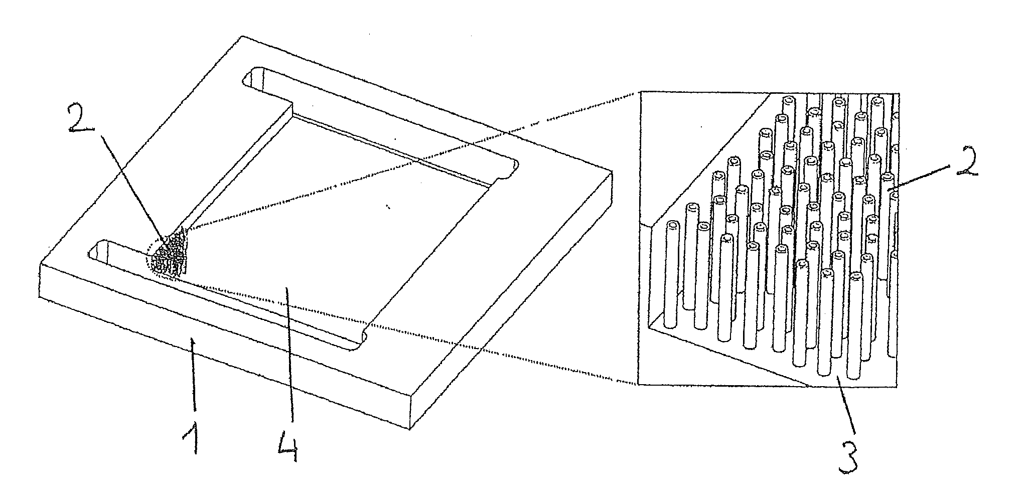
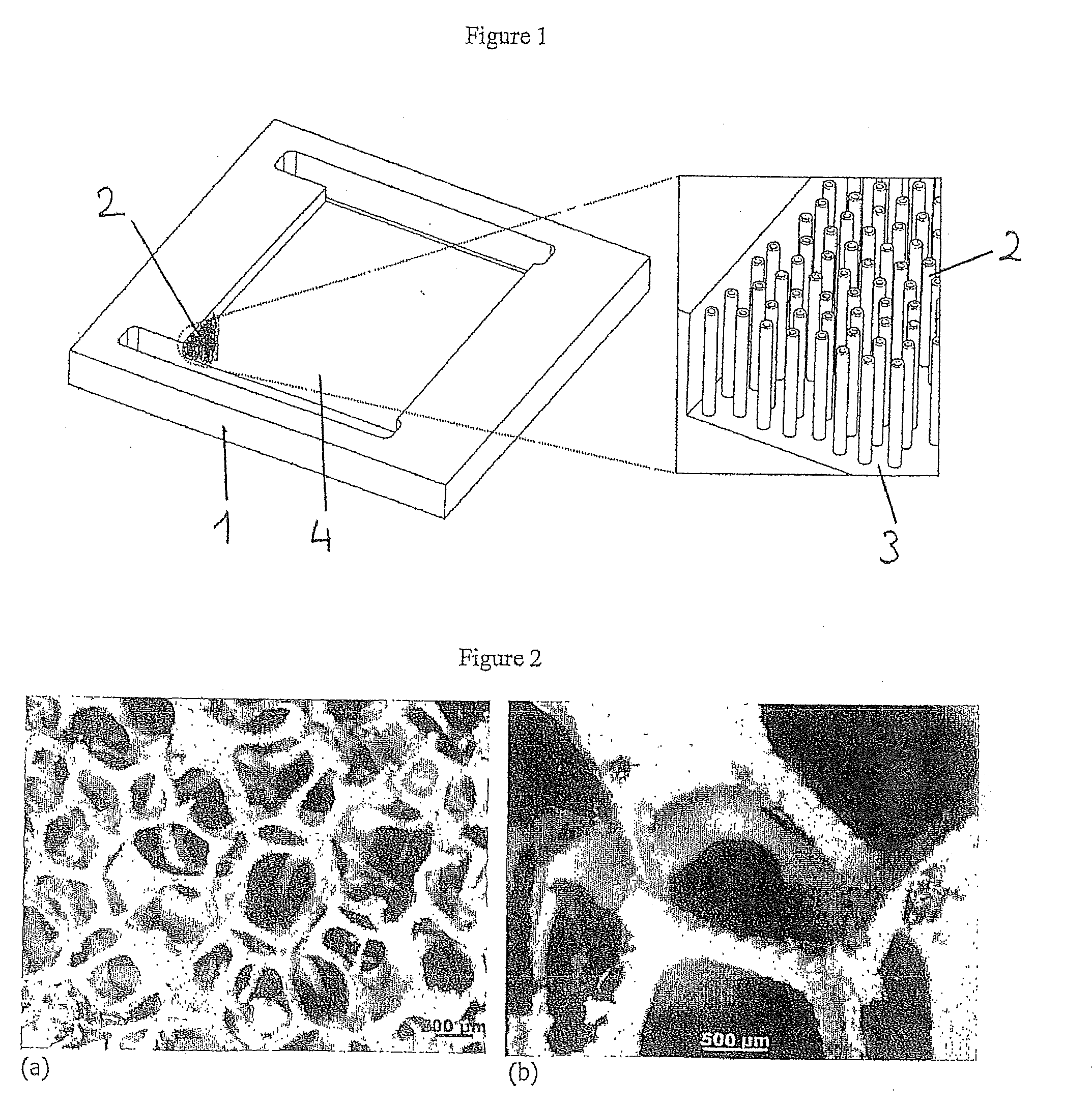
[0143]To prepare the main panel of the microreactor, a part made of heat-resistant steel is cut to the dimensions 50×40×5 mm whereon a 34×28×2 mm channel is machined. At both ends of the channel, two rectangular openings are produced and used as the gas mixing space and for a gas inlet and outlet. The channels are connected to reagent admission systems on either side of the panel.

[0144]The steel panel channel is subsequently coated by means of spin coating or with a pipette with a thin layer of HSQ (hydrogen silsesquioxane) which is subsequently converted into SiO2 by means of heat treatment for 4 hours at 400° C. The 200 nm thick SiO2 layer is a substrate for the nucleation and growth of the carbon nanotubes.

[0145]The growth of the aligned carbon nanotubes in the channel is performed by means of CCVD (Chemical Catalytic Vapour Deposition) in the tubular reactor by circulating a mixture containing ferrocene (purity: 99%, Strem Che...

example 2

Photocatalytic Phase Deposition

[0156]A SiC nanofibre / SiC foam composite filling the channels of the microreactor, coated very homogeneously with an active phase, TiO2 (FIG. 8), was produced. The TiO2 nanoparticles cover the SiC nanofibre superstructure with an excellent mechanical resistance demonstrated by a lack of TiO2 loss after 30 minutes of sonication. TiO2 particle deposition was performed directly during TiO2 synthesis using a sol-gel process. For this, the SiC nanofibre / SiC foam composite is impregnated with an ethanol (1.4 ml / g SiC) / titanium tetraisopropoxide (0.65 ml / g SiC) solution. The synthesis of the sol-gel, directly on the composite, is then performed by circulating water vapour (obtained by bubbling air in a saturator containing liquid water at ambient temperature) at a flow rate of 100 ml / min. In contact with moisture, gelling is performed to form a titanium hydroxide. The whole is then calcined at 350° C. for 2 hours to obtain the final hierarchised material with...

example 3

Catalysis Application

[0157]A reactor according to the invention was used for the methanol dehydration reaction to dimethyl ether. The catalyst used in this reaction is zeolite ZSM-5 (MFI family) deposited directly on the surface of the substrates by means of hydrothermal synthesis at 170° C. for 48 hours. The substrates were:

[0158]A: an alveolar β-SiC foam;

[0159]B: the same alveolar β-SiC foam coated with SiC nanofibres.

[0160]In both cases, the concentration of zeolite H-ZSM5 was 30% by mass in relation to the mass of the catalyst. The reaction was performed at 270° C. with 0.2 ml of liquid methanol per minute and an argon gas stream at 80 ml / min. It is noted that the conversion rate exceeds 50% in the presence of SiC nanofibres, whereas it barely exceeds 30% in the absence of SiC nanofibres (see FIG. 10).

[0161]This improvement in the conversion yield of the substrate (b) is probably associated with the greater specific surface area thereof.


PUM


Abstract

The invention relates to a chemical reactor with a nanometric superstructure, comprising at least one member wherein at least one reaction chamber is arranged, and said reaction chamber being filled at least partially with a high specific surface area material having a specific surface area greater than 5 m2/g, and characterised in that said high specific surface area material is selected from nanotubes or nanofibres.
These nanotubes or nanofibres are preferably selected in the group consisting of carbon nanofibres or nanotubes, β-SiC nanofibres or nanotubes, TiO2 nanofibres or nanotubes.
They may be deposited on an intermediate structure selected in the group consisting of glass fibres, carbon fibres, SiC foams, carbon foams, alveolar β-SiC foams, said intermediate structure filling the reaction chamber of said reactor at least partially.

Description

FIELD OF THE INVENTION[0001]The present invention relates to the field of chemical reactors, and more specifically the field of catalytic or photocatalytic reactors.STATE OF THE RELATED ART[0002]In recent years, chemical engineering specialists have placed specific interest in microreactors, both catalytic and not. The reasons for this are multiple: in catalysis, the small size thereof results in a large surface area to volume ratio, promoting contact with the reagents and the active sites in a laminar flow mode. In a small reactor, mass and heat transfer phenomena are significantly exacerbated and produce isothermal reactions with no diffusion, giving rise to an almost instantaneous equilibrium of the reagent concentration at any point of the system, and a high level of temperature homogenisation in the catalytic bed. The superior temperature control makes it possible to improve installation securing problems during start-up stages very significantly, particularly for highly exothe...

Claims


Application Information

Patent Timeline
Patent Type & Authority Applications(United States)
IPC IPC(8): B01J19/00C07C41/09C01B31/36C01G23/047C23C16/06B01D15/04B82Y30/00B82Y40/00
CPCB01J19/0093B01J21/063B01J21/08B01J21/185C01B31/20B01J29/40B01J2219/00846B82Y30/00B01J23/755C01B32/50
Inventor PHAMHUU, CUONGKELLER, NICOLASLEDOUX, MARC JACQUESJANOWSKA, IZABELLAEDOUARD, DAVIDKELLER-SPITZER, VALERIEROMERO, THIERRYYU, LIU
Owner CENT NAT DE LA RECHERCHE SCI
Why Eureka
Try Eureka