Efficient Use Of Flash Memory In Flash Drives

Active Publication Date: 2011-06-16
SMSC HLDG
View PDF28 Cites 53 Cited by
  • Summary
  • Abstract
  • Description
  • Claims
  • Application Information

AI Technical Summary

Benefits of technology

[0020]FIG. 6B is a flowchart illustrating actions of an exemplary method of operating a USB Host Device, such as the USB Host Device of FIG. 2, to enable the USB Host Device to complete an access initiated as described above with respect to FIG. 6A, in order to efficiently access the flash memory devices in a USB flash drive such as the USB flash drive device of FIG. 2, in accordance with a representative embodiment of the present invention.
[0021]FIG. 7A is a flowchart illustrating actions of an exemplary method of processing command messages for accesses to a USB flash drive device, such as the USB flash drive device

Problems solved by technology

Therefore, block erase time is a significant factor that limits the ability to write data to memory in systems that employ flash memory devices.
Flash memory has a limited life when compared to other forms of read-write memory.
Frequent accesses to the same locations in memory due to, for example, operating system updates to file system data structures, however, can cause failure of flash memory devices within an unacceptably short period of time.
In reality, requests may come in any order and bank conflicts may arise.
While present day flash-based solid state drives (SSDs) do include temporary storage for pending commands, conventional USB flash drives do not use on-chip buffers to hold data for commands / transactions for which the required banks are not available, and throughput for such devices is degraded.
Sufficient buffer memory must then be available to store all of the data for commands waiting for access to the required banks, and the cost of such buffers becomes prohibitively expensive.

Method used


Image

  • Efficient Use Of Flash Memory In Flash Drives
  • Efficient Use Of Flash Memory In Flash Drives
  • Efficient Use Of Flash Memory In Flash Drives

Examples


Embodiment Construction

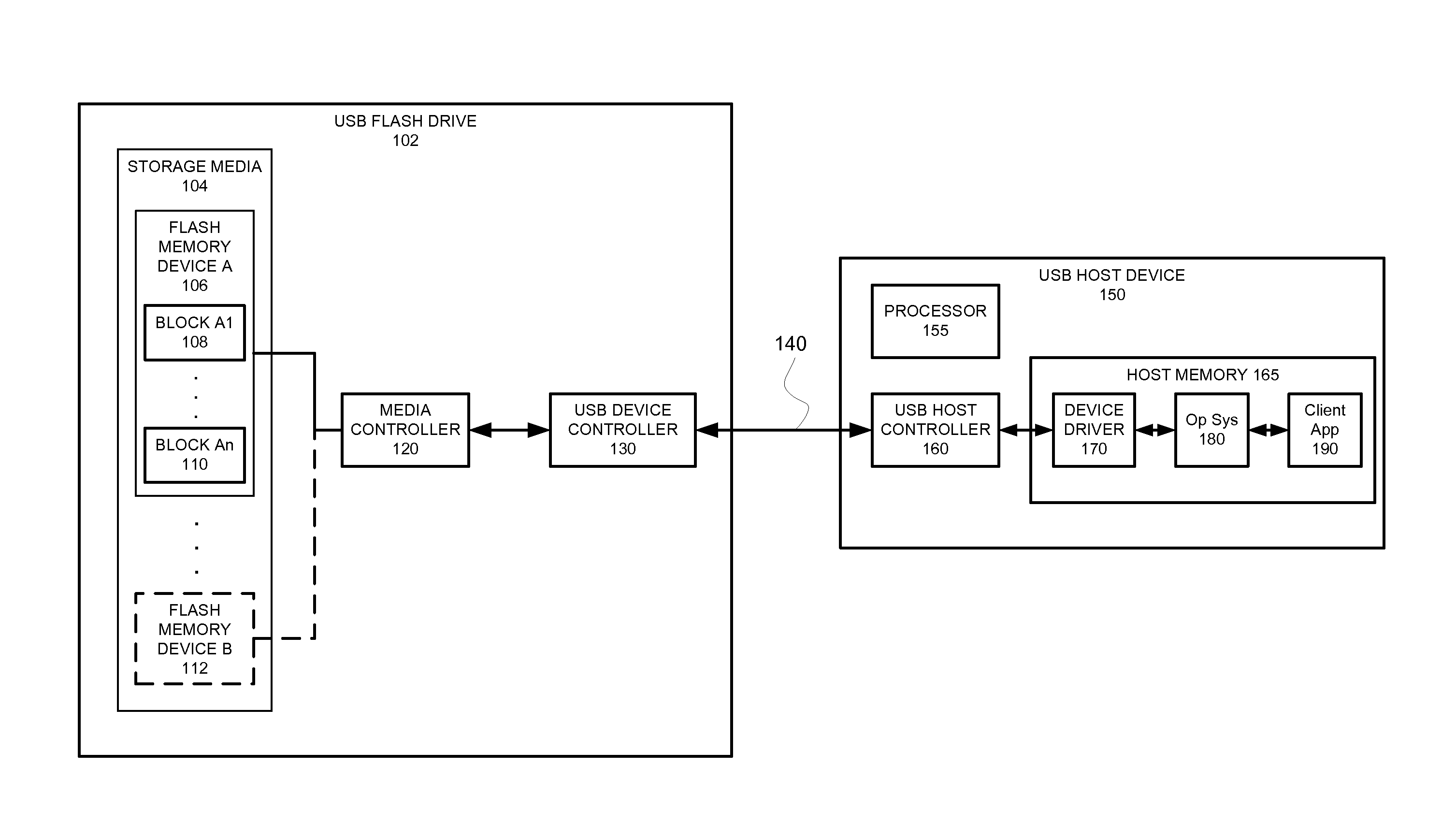
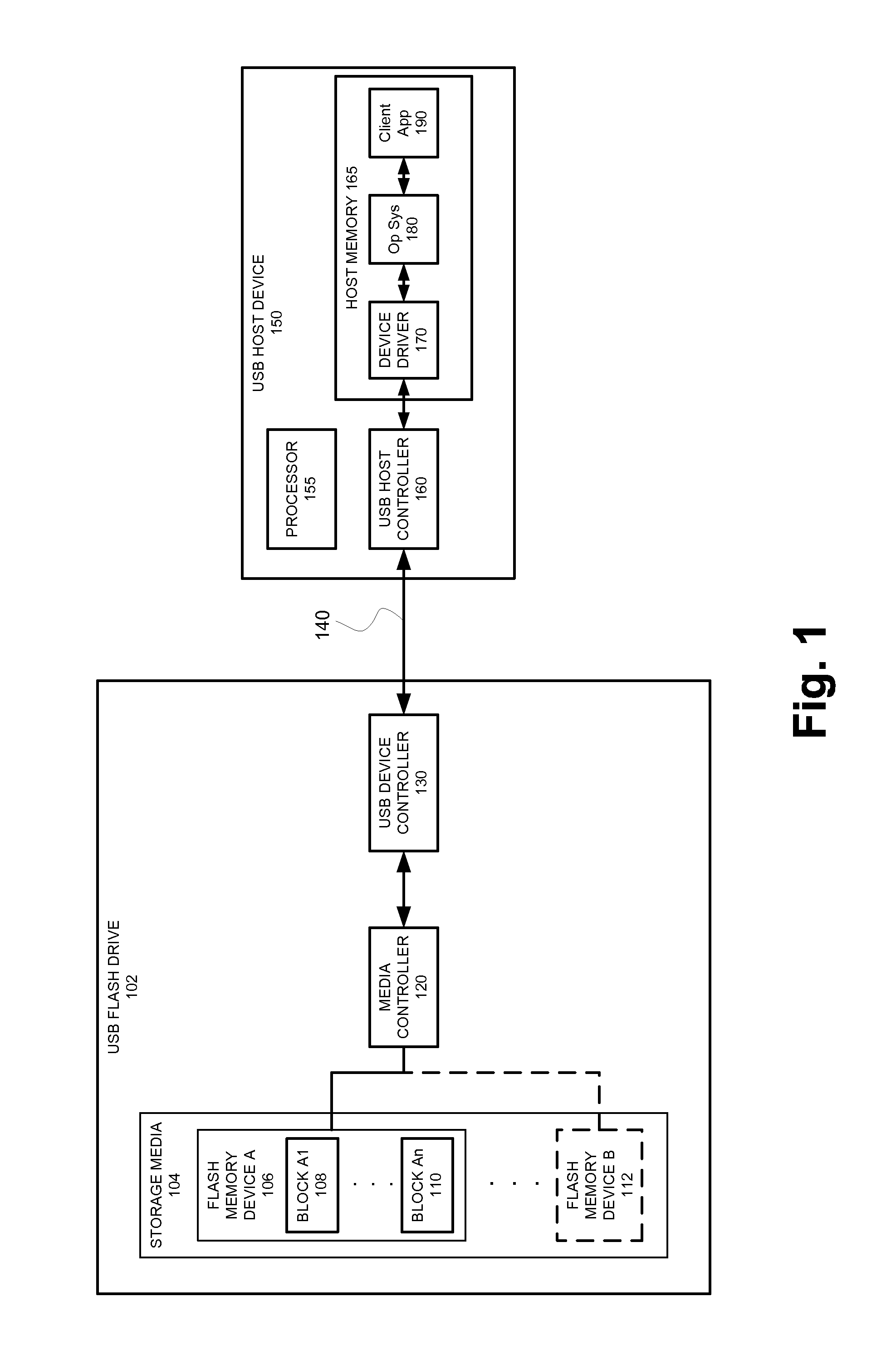
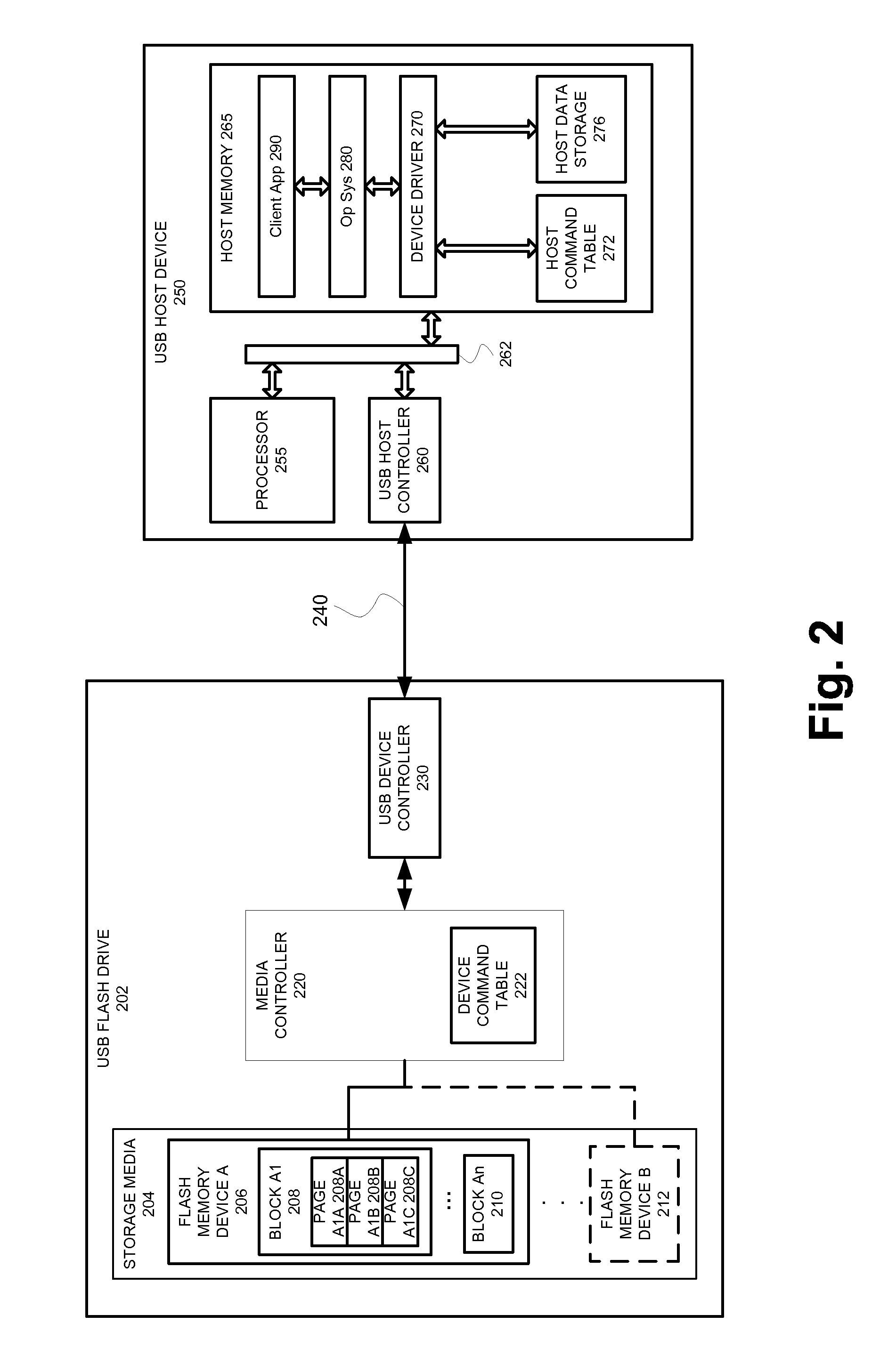
[0023]Aspects of the present invention relate in general to reading and writing of data to non-volatile memory devices. More specifically, aspects of the present invention relate to devices, systems, and methods that enable a host device such as, for example, a personal / laptop / notebook / netbook computer (PC), personal digital assistant (PDA), a mobile / cellular phone, and a desktop computer to efficiently read data from and write data to a flash memory-based, non-volatile, data storage device frequently referred to as a “flash drive,” which are also known by the terms “USB key,”“pen drive,”“Thumb Drive®,”“DiskOnKey®,” and “Jump Drive®.”

[0024]Although the following discussion makes frequent reference to the use of the disclosed devices and techniques in embodiments of a USB flash drive, the inventive concepts presented herein are not specifically limited only to that use, and may find application in other electronic devices known now or in the future.

[0025]The term “flash memory” is us...


PUM


Abstract

A data storage device having non-volatile solid state memory permits efficient access by permitting multiple pending commands from a host device. A controller in the data storage device stores information about each command from the host device, and determines which stored command, if any, is presently able to be performed based on the portion of the non-volatile memory and the type of access of the command. The data storage device provides reduced access delays, improves read / write throughput, and avoids the cost of additional memory in the data storage device, by allowing accesses to idle portions of memory to proceed, and by signaling the host device when the data storage device is able to accept data to be written to portions of the non-volatile memory already active due to a previous command.

Description

RELATED APPLICATIONS[0001][Not Applicable]FEDERALLY SPONSORED RESEARCH OR DEVELOPMENT[0002][Not Applicable]MICROFICHE / COPYRIGHT REFERENCE[0003][Not Applicable]BACKGROUND OF THE INVENTION[0004]A “USB flash drive” is a portable, read / write, non-volatile, solid-state memory device that may be connected to and accessed over a Universal Serial Bus (USB) connection. A USB flash drive is also sometimes referred to as a “USB key”, “pen drive”, “Thumb Drive®”, “DiskOnKey®”, and “Jump Drive®”. The popularity of USB flash drives has grown rapidly, as has USB flash drive capacity. A USB flash drive is a specific instance of a larger class of devices referred to as “USB mass storage devices.”[0005]The generic name of “USB flash drive” used to refer to these types of USB mass storage devices comes from the type of non-volatile, solid state memory used as the medium in which to store the data they contain. USB flash drive sizes have grown rapidly, tracking the increased density of available flash ...

Claims


Application Information

Patent Timeline
IPC IPC(8): G06F12/00G06F12/02G06F13/00
CPCG06F12/00G06F13/00G06F12/02G06F13/385G06F2213/3812G06F2213/3854
Inventor INTRATER, GIDEON DAVID
Owner SMSC HLDG
Why Eureka
Try Eureka