Hands-free step-in closure apparatus

Active Publication Date: 2011-06-23
KAUFMAN STEVEN
View PDF36 Cites 74 Cited by
  • Summary
  • Abstract
  • Description
  • Claims
  • Application Information

AI Technical Summary

Benefits of technology

[0008]In view of the above-described problems, it is an object of the present disclosure to provide a means of quickly and securely fastening footwear to a user's feet via a simple, reversible, and hands-free operating mechanism. This is accomplished by a fas

Problems solved by technology

However, each of these fasteners typically requires the use of one's hands for efficient operation.
This may

Method used


Image

  • Hands-free step-in closure apparatus
  • Hands-free step-in closure apparatus
  • Hands-free step-in closure apparatus

Examples


Example

First Embodiment

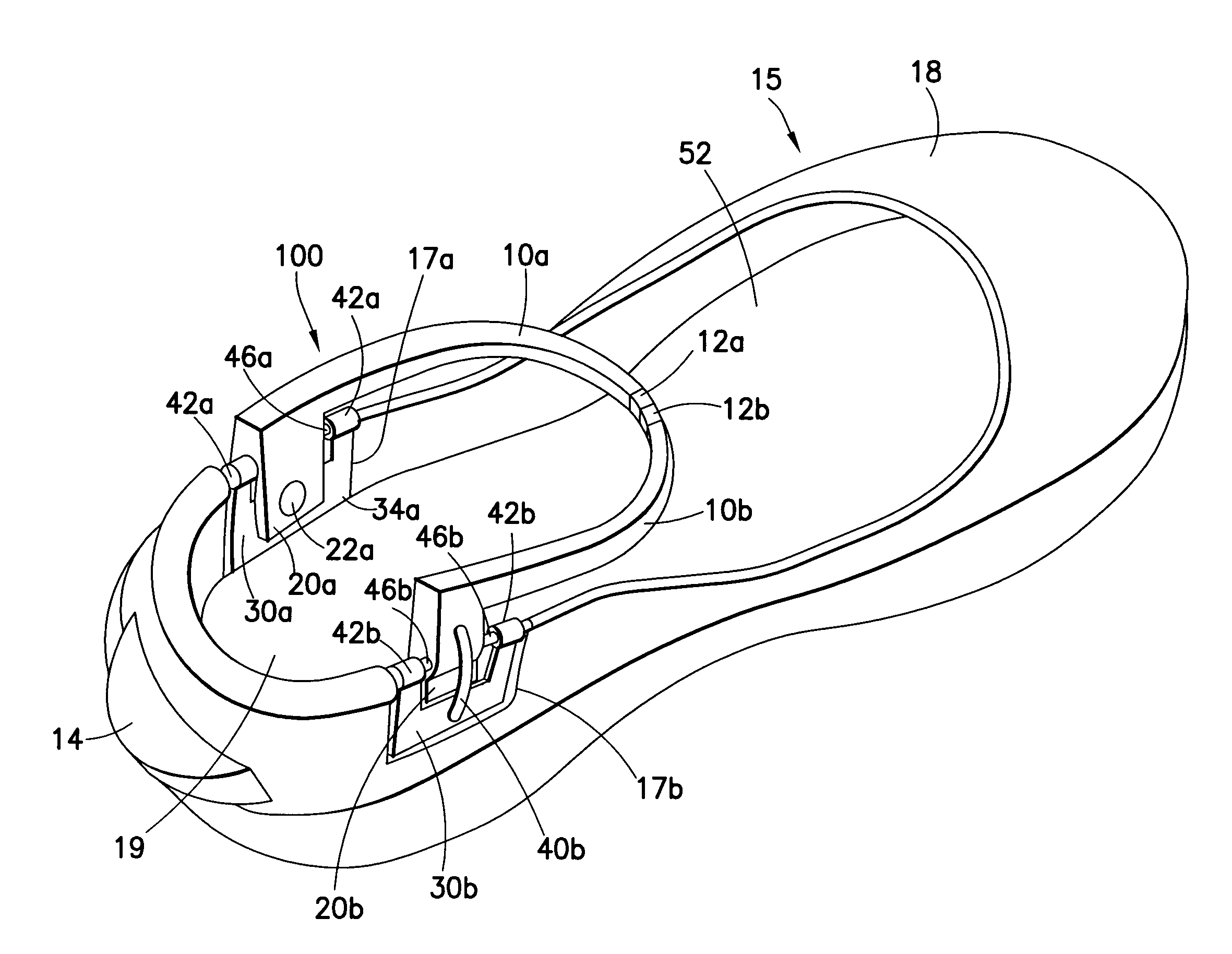
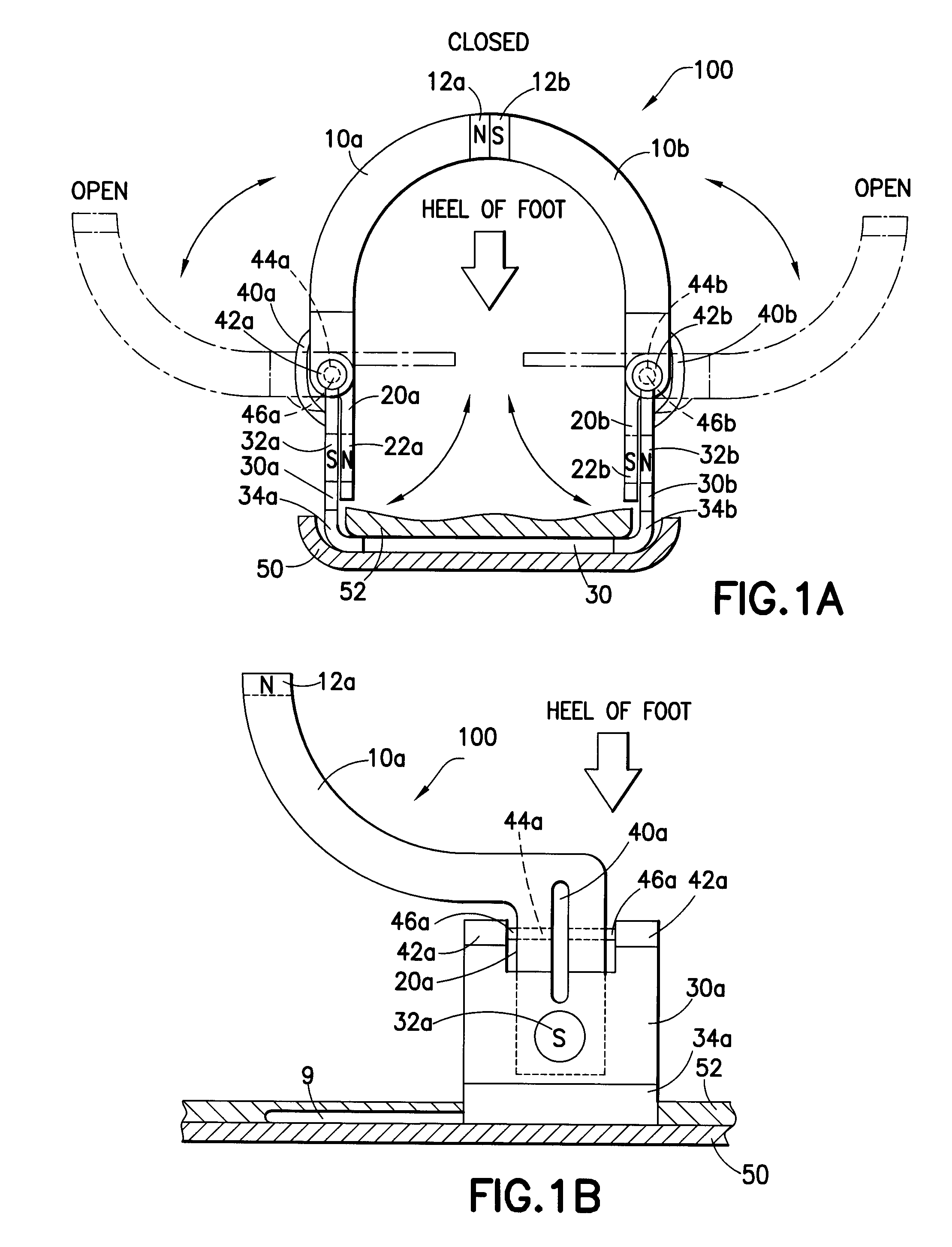
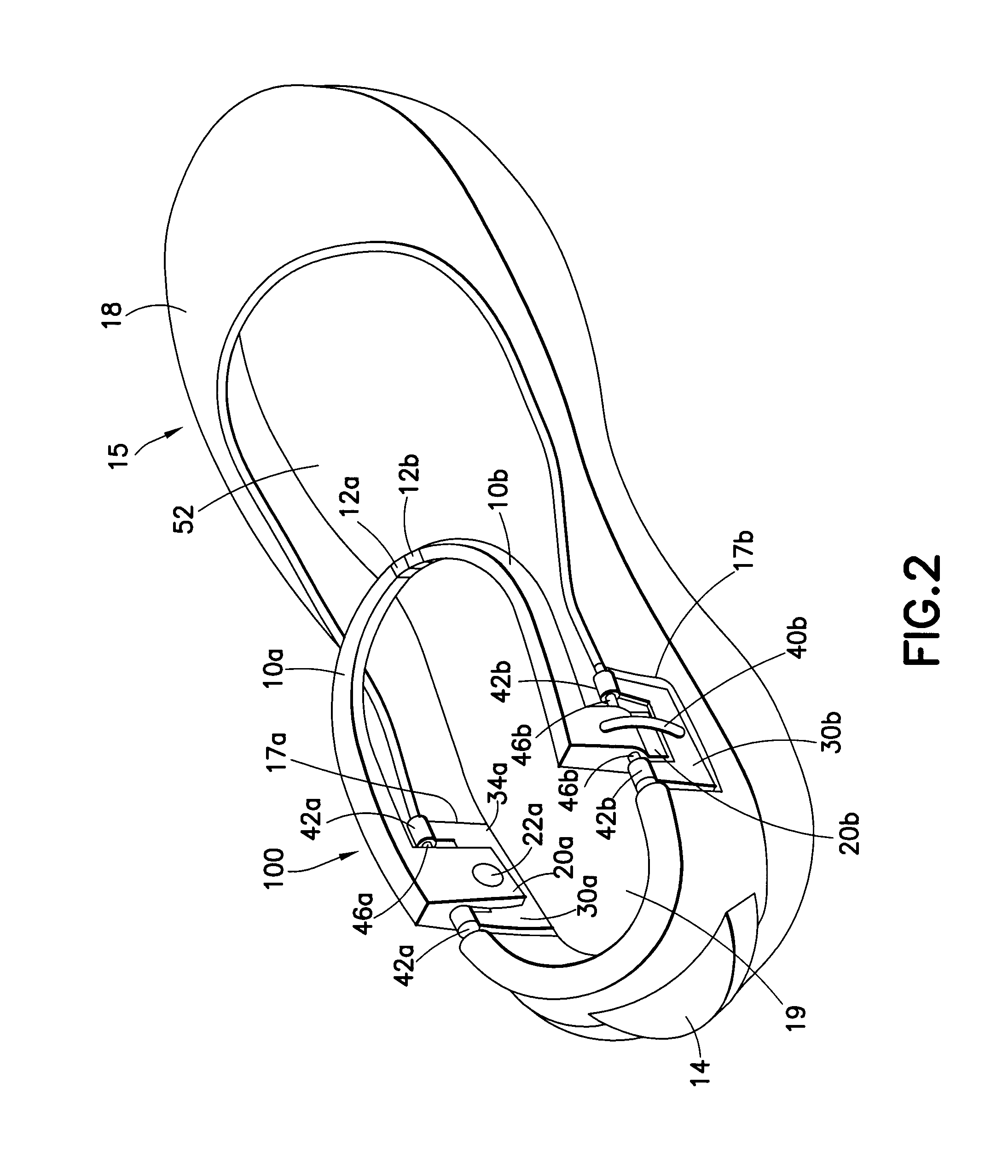
[0050]FIG. 1A is a schematic showing a rear view of a first embodiment of a fastening device 100. The fastening device 100 shown in FIG. 1A comprises two straps 10a and 10b which are positioned on the left and right side of the user's foot, respectively. The straps are individually affixed to left 20a and right 20b levers which are, in turn, secured to corresponding left 30a and right 30b arms of a support bracket 30 (which, in this embodiment, is U-shaped) by means of a hinge rod (46a and 46b which passes through a hinge located on each lever. The hinge rods are, in turn, secured to the support bracket by attachment points located on the end of each arm of the support bracket. Thus lever 20a is attached to arm 30a by hinge rod 46a which passes through hinge 44a and is secured at attachment points 42a. Likewise, lever 20b is attached to arm 30b by hinge rod 46b which passes through hinge 44b and is secured at attachment points 42b.

[0051]The combined strap / lever comp...

Example

[0059]A second embodiment of the fastening device 200 will now be described in detail with reference to FIGS. 3A and 3B. The underlying principles governing operation of the second embodiment are similar to those presented above for the first embodiment, but the mechanics differ. Here, the hinge rods 46a and 46b are aligned approximately perpendicular instead of approximately parallel to the base of the support bracket 30 and the user's foot engages the levers by sliding forward instead of stepping downwards.

[0060]The fastening device 200 comprises components analogous to those disclosed for the fastening device 100 of the first embodiment. FIG. 3A is a rear view of the fastening device 200 showing the inclusion of left 10a and right 10b straps with corresponding left 20a and right 20b levers. The straps 10a and 10b are respectively secured to the left 30a and right 30b arms of support bracket 30 by means of hinge rods 46a and 46b which pass through hinges 44a and 44b and are secure...

Example

Third Embodiment

[0066]A front perspective view of a schematic illustrating a third embodiment of the fastening device 300 is provided in FIG. 4. The fastening device 300 comprises a structure and operating mechanism similar to that provided in the first embodiment, but includes a number of additional design features. For instance, each strap 10a and 10b is attached to, but physically separate from the left 20a and right 20b levers. Additionally, each lever 20a and 20b may be removed from its corresponding support bracket 30a and 30b by disengaging interior hinge rods 48a and 48b, respectively. Finally, the support brackets 30a and 30b themselves are designed such that they may be built (i.e., permanently incorporated) into the footwear during manufacture.

[0067]FIG. 4 shows that the posterior ends of each strap 10a and 10b form oval cylinders 33a and 33b, respectively, which fit into and are capable of sliding through a matching bore situated at the top of the left 20a and right 20b ...


PUM


Abstract

A hands-free fastening mechanism for releasably securing a user's foot to footwear is disclosed. The fastening mechanism comprises at least one pivotable strap which is coupled to a hinge mechanism which, in turn, is secured to the footwear. The hinge mechanism allows the strap to pivot between an open and a closed position. The strap is further coupled to a lever which is engageable by a user's foot so as to cause the strap to move from the open position to the closed position. When the strap moves to the closed position, a catch will engage, thereby securing the user's foot within the footwear. The footwear may then be removed by using the other foot to apply pressure to a protruding member or by striking the heel on a hard surface and then withdrawing the secured foot such that the catch is disengaged and the foot is released.

Description

CROSS-REFERENCE TO RELATED APPLICATIONS[0001]This application is a continuation-in-part of U.S. patent application Ser. No. 12 / 172,609 filed Jul. 14, 2008, which claims priority under 35 U.S.C. §119(e) to U.S. Provisional Patent Application No. 61 / 068,145 filed on Mar. 5, 2008, the entirety of all of which are herein incorporated by reference.BACKGROUND[0002]1. Field of the Disclosure[0003]This disclosure relates generally to the field of foot bindings. In particular, the present disclosure relates to a hands-free mechanism suitable for securing and releasing an article about a user's foot.[0004]2. Description of the Related Art[0005]Over the course of human history there has been a continuing and ever-present need to utilize various types of footwear suitable for differing purposes. For example, athletic shoes typically comprise a rubber sole combined with a lightweight, breathable mesh upper; work boots are frequently made of a tough rubber sole, leather upper, and are reinforced ...

Claims


Application Information

Patent Timeline
IPC IPC(8): A43B21/00A43C11/00A43B13/38
CPCA43C11/00A43B11/00A43C11/008
Inventor KAUFMAN, STEVEN
Owner KAUFMAN STEVEN
Why Eureka
Try Eureka