
Thin-film solar cell and manufacture method thereof

Inactive Publication Date: 2011-06-23
AURIA SOLAR CO LTD
View PDF2 Cites 11 Cited by
  • Summary
  • Abstract
  • Description
  • Claims
  • Application Information

AI Technical Summary

Benefits of technology

[0009]The present invention provides a thin-film solar cell, which can enhance the utilization factor of light beams to improve the photoelectric conversion efficiency of the thin-film solar cell.
[0029]According to the above descriptions, the thin-film solar cell of the present invention has a light reflecting structure disposed on the second transparent conductive layer to increase the opportunity for the light beam to be reflected in the thin-film solar cell. This can prolong the light path of the light beam in the photovoltaic layer so that the light beam will be more likely absorbed by the photovoltaic layer to generate more electron-hole pairs. In other words, the thin-film solar cell employing the light reflecting structure can effectively enhance the utilization factor of the light beam to improve the photoelectric conversion efficiency thereof.
[0030]The present invention also provides a method for manufacturing a thin-film solar cell, which can form a light reflecting structure having a texture structure on a layer. This can enhance the utilization factor of the light beam in the thin-film solar cell, thus resulting in improved photoelectric conversion efficiency of the thin-film solar cell.
[0045]According to the above descriptions, the method for manufacturing a thin-film solar cell of the present invention forms a light reflecting structure having a texture structure on the second transparent conductive layer to increase the opportunity for the light beam to be reflected in the thin-film solar cell. This can prolong the light path of the light beam in the photovoltaic layer so that the light beam will be more likely absorbed by the photovoltaic layer to generate more electron-hole pairs. In other words, the method for manufacturing a thin-film solar cell of the present invention can effectively enhance the utilization factor of the light beam in the resulting thin-film solar cell, thus improving the photoelectric conversion efficiency of the thin-film solar cell.

Problems solved by technology

However, thin-film solar cells currently available have photoelectric conversion efficiency as low as about 6%˜10% on average, and currently there still exists a bottleneck in improving the photoelectric conversion efficiency of the thin-film solar cells.

Method used


Image

  • Thin-film solar cell and manufacture method thereof
  • Thin-film solar cell and manufacture method thereof
  • Thin-film solar cell and manufacture method thereof

Examples


Embodiment Construction

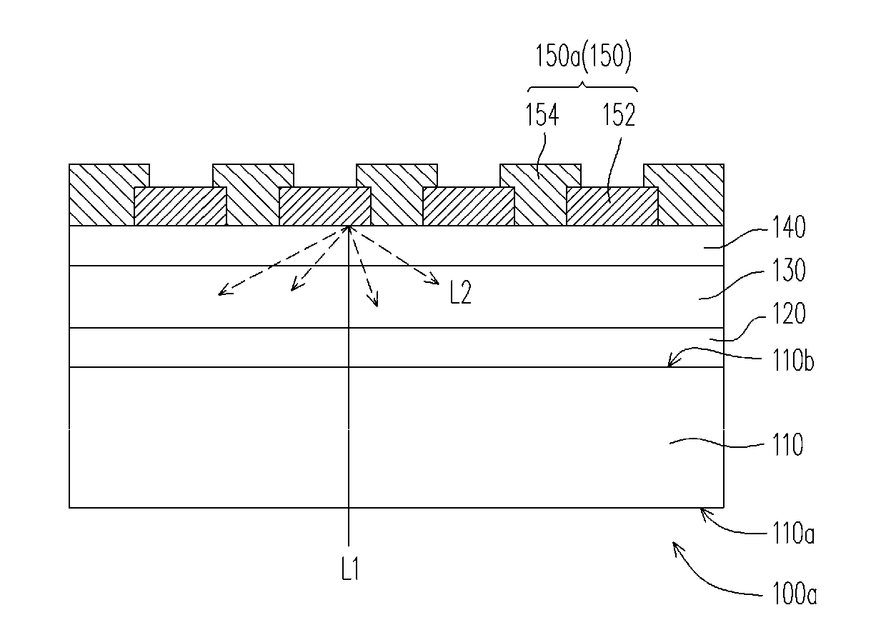
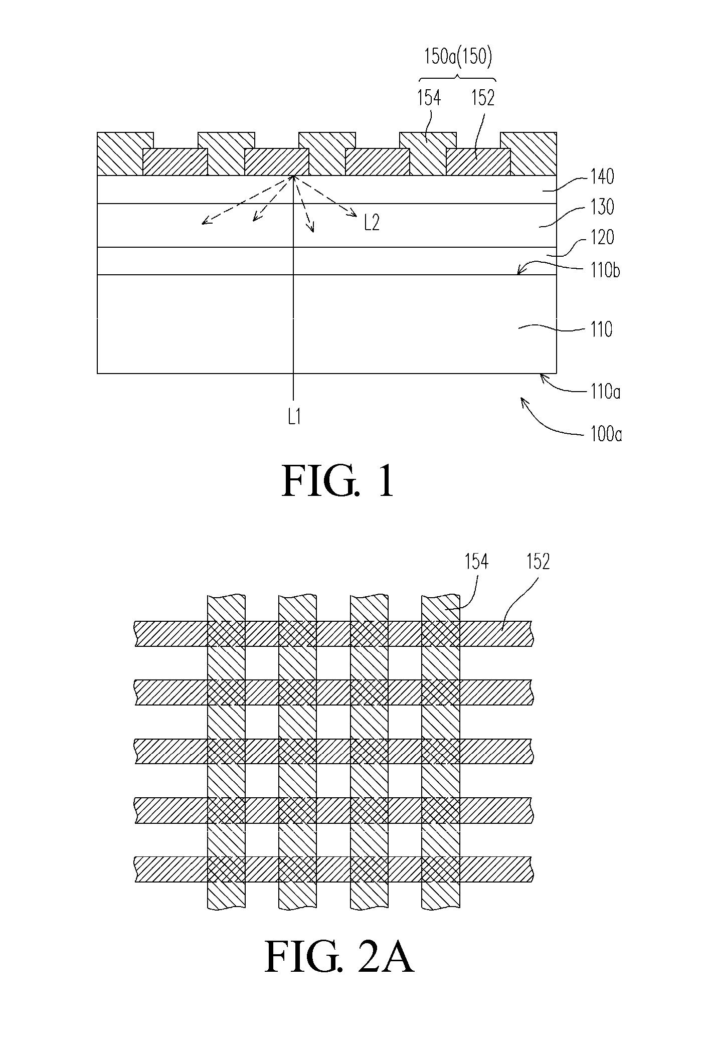
[0061]FIG. 1 is a schematic cross-sectional view of a thin-film solar cell according to an embodiment of the present invention. Referring to FIG. 1, in this embodiment, the thin-film solar cell 100a comprises a transparent substrate 110, a first transparent conductive layer 120, a photovoltaic layer 130, a second transparent conductive layer 140 and a light reflecting structure 150.

[0062]The transparent substrate 110 has a light incident surface 110a and a light exiting surface 110b opposite to the light incident surface 110a. The transparent substrate 110 is, for example, a glass substrate. The first transparent conductive layer 120 is disposed on the light exiting surface 110b of the transparent substrate 110. The photovoltaic layer 130 is disposed on the first transparent conductive layer 120. The second transparent conductive layer 140 is disposed on the photovoltaic layer 130. The light reflecting structure 150 is disposed on the second transparent conductive layer 140. A light...


PUM


Abstract

A thin-film solar cell and a manufacture method thereof are provided. The thin-film solar cell comprises a transparent substrate, a first transparent conductive layer, a photovoltaic layer, a second transparent conductive layer and a light reflecting structure. The transparent substrate has a light incident surface and a back surface opposite to the light incident surface. The first transparent conductive layer is disposed on the back surface of the transparent substrate. The photovoltaic layer is disposed on the first transparent conductive layer. The second transparent conductive layer is disposed on the photovoltaic layer. The light reflecting structure is disposed on the second transparent conductive layer. The manufacture method forms the light reflecting structure having a texture structure on the thin film to enhance utilization of light beams in the thin-film solar cell so as to further improve photoelectric conversion efficiency of the thin-film solar cell.

Description

[0001]This application claims priority to Taiwan Patent Applications No. 099107834 and No. 099107836 filed on Mar. 17, 2010, which are hereby incorporated by reference in their entirety.CROSS-REFERENCES TO RELATED APPLICATIONS[0002]Not applicable.BACKGROUND OF THE INVENTION[0003]1. Field of the Invention[0004]The present invention relates to a solar cell and a manufacturing method thereof, and more particularly, to a thin-film solar cell with improved photoelectric conversion efficiency and a manufacturing method thereof.[0005]2. Descriptions of the Related Art[0006]Due to shortage of fossil energy resources and enhanced awareness of environmental protection, great efforts have been made continuously in recent years on development and research of technologies related to alternative energy resources and renewable energy resources. This is intended to reduce the level of dependence on fossil energy resources and influence of consumption of fossil energy resources on the environment. A...

Claims


Application Information

Patent Timeline
IPC IPC(8): H01L31/0232H01L31/18
CPCH01L31/02167H01L31/02168H01L31/056H01L31/0236Y02E10/52H01L31/022466
Inventor TSAI, CHIN-YAO
Owner AURIA SOLAR CO LTD
Learn More