Device for fixing conductor tracks on a solar cell

a solar cell and track technology, applied in the direction of gas flame welding apparatus, non-electric welding apparatus, auxiliary devices for welding, etc., can solve the problems of difficult to bring into the desired surface contact (fixation) with the upper surface, the construction of the hold-down device is complex, and the conductor track can easily be damaged, etc., to achieve optimized (steady) transport and high clock rate

Inactive Publication Date: 2011-06-23
KIOTO PHOTOVOLTAICS
View PDF6 Cites 10 Cited by
  • Summary
  • Abstract
  • Description
  • Claims
  • Application Information

AI Technical Summary

Benefits of technology

[0034]The speed by which the crossbar is moved from the staring position into the operating position can be degressive, that means decreasing towards the end to prevent that the hold-down devices shift the conductor tracks if there is not a 100% alignment of crossbar and solar cells.
[0035]The transport installation can include at least one product carrier on which the solar cells (or a solar cell-string) lie. The carriers can have bridge-like ridges on their surface pointing towards the solar cells that are arranged in such a manner that the conductor tracks which

Problems solved by technology

This is difficult inter alia because the solar cells are extremely thin (approximately 200 μm) and brittle and the conductor tracks with a width of for example 0.5 to 3 mm and a thickness of not more than 0.2 to 1 mm are thin strips, which cannot be brought easily into the desired surface contact (fixation) with the upper surface/lower surface of the solar cell.
The known hold-down device is constructionally ver

Method used


Image

  • Device for fixing conductor tracks on a solar cell
  • Device for fixing conductor tracks on a solar cell
  • Device for fixing conductor tracks on a solar cell

Examples


Embodiment Construction

process in which at least one string is soldered at a time.

[0036]Further features of the invention result from the features of the sub claims as well as the other application documents.

BRIEF DESCRIPTION OF THE DRAWINGS

[0037]The invention is explained in more detail hereinafter by one embodiment. This shows, each in a schematic illustration:

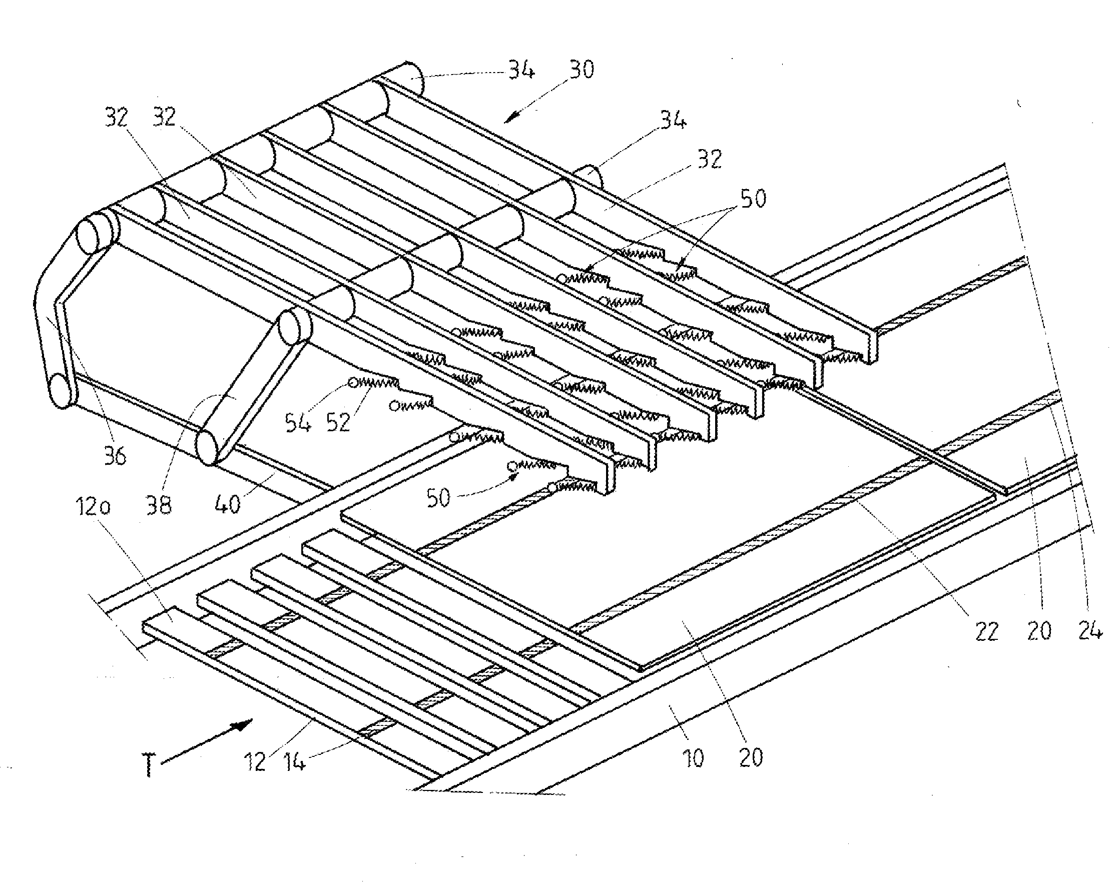
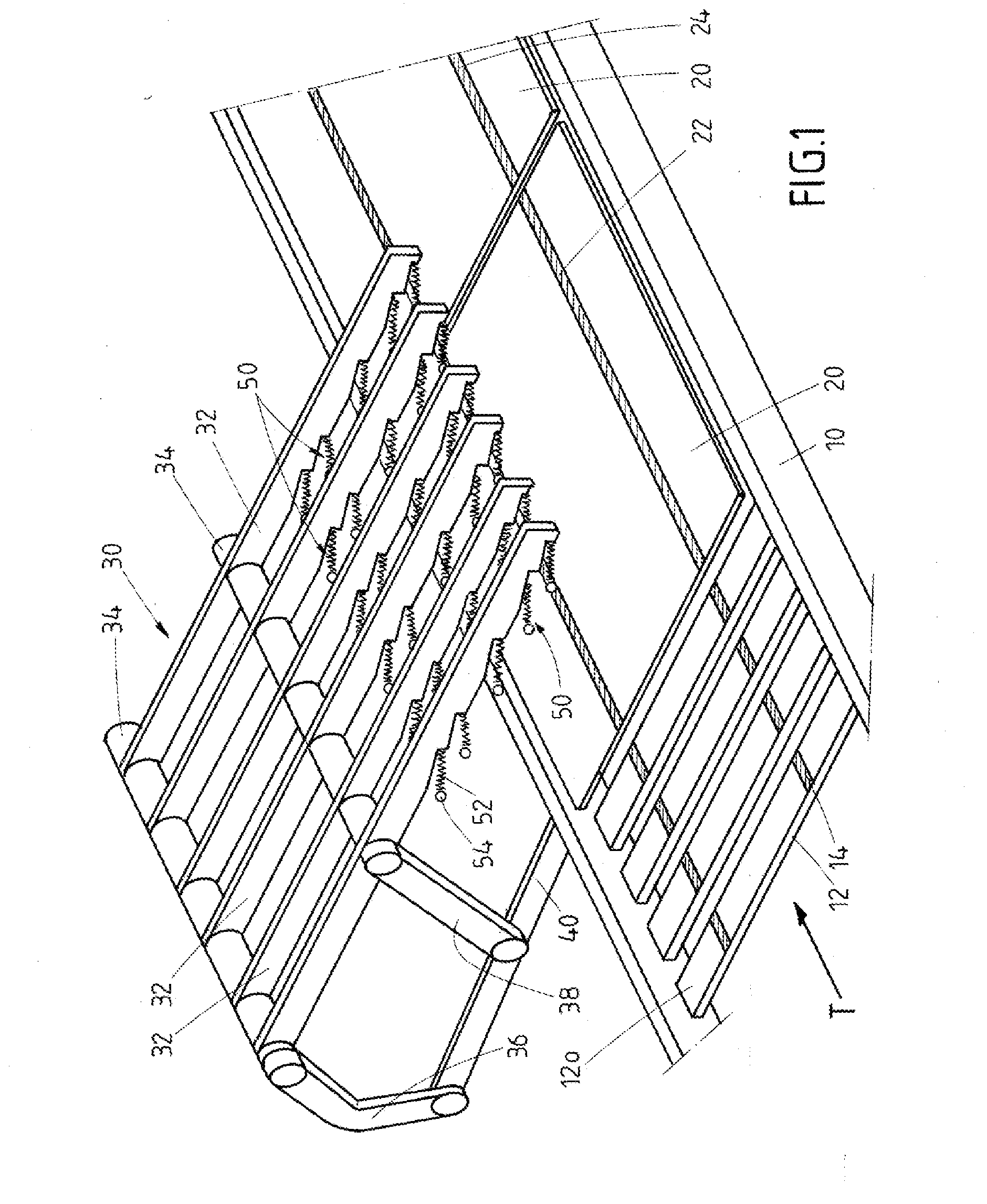
[0038]FIG. 1: A perspective view of a device according to the invention,

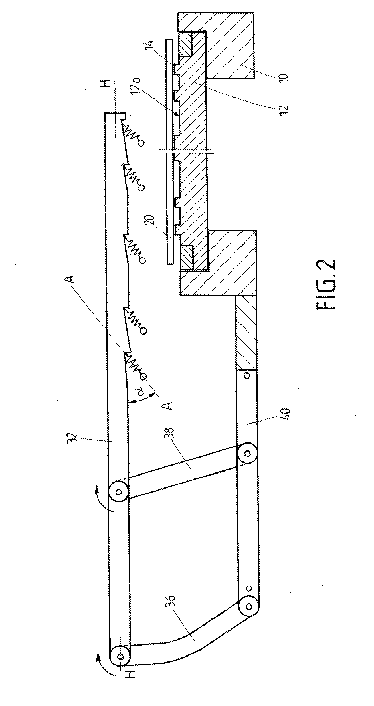
[0039]FIG. 2: a side view of the device according to FIG. 1 in the starting position,

[0040]FIG. 3: a partial sectional view through the device according to FIG. 1 in an operating position,

[0041]FIG. 4: a cross-section through a conductor track,

[0042]FIG. 5: a side view of a hold-down device attached to a crossbar.

[0043]In the Figures components which are similar or with similar effect are illustrated by the same numerals.

DETAILED DESCRIPTION OF PREFERRED EMBODIMENT

[0044]The device includes a transport system the transport direction of which is characterized by arrow T. The tra...


PUM

PropertyMeasurementUnit
Temperatureaaaaaaaaaa
Angleaaaaaaaaaa
Angleaaaaaaaaaa

Abstract

The invention concerns to a device for fixing conductor tracks on at least one first main-surface of at least one solar cell.

Description

FIELD OF THE INVENTION[0001]The invention relates to a device for fixing conductor tracks (conductor strips) on at least one first main-surface of at least one solar cell.BACKGROUND OF THE INVENTION[0002]Usually at least two conductor tracks (conductor paths) extend parallel to each other on a solar cell (photovoltaic-cell), wherein a pair (2) of conductor tracks connect a first main-surface (upper side) of a solar cell with a second main-surface (lower side) of an adjacent solar cell. A series of solar cells connected in this manner form a so called solar cell string, accordingly providing the following features:[0003]this string comprises a series of solar cells arranged in succession,[0004]adjacent solar cells are connected by at least two electrical conductor tracks,[0005]each conductor track is firmly connected with a first section to an upper surface of a solar cell and with a second section to a lower surface of the adjacent solar cell.[0006]Usually the conductor tracks have ...

Claims


Application Information

Patent Timeline
IPC IPC(8): B23K37/04
CPCB23K1/0008B23K2201/40B23K37/0408B23K3/087B23K2101/40
Inventor EUSCH, INGRAMFRANK, RUDOLFKOGLER, ARMIN
Owner KIOTO PHOTOVOLTAICS
Why Eureka
Try Eureka