OLED device with capacitive proximity sensing means

a capacitive proximity and sensor technology, applied in electronic switching, pulse technique, instruments, etc., can solve the problem that current oled devices do not integrate tactile feedback, and achieve the effect of large dynamic range and motion

Inactive Publication Date: 2011-06-23
KONINKLIJKE PHILIPS ELECTRONICS NV +1
View PDF12 Cites 42 Cited by
  • Summary
  • Abstract
  • Description
  • Claims
  • Application Information

AI Technical Summary

Benefits of technology

[0007]Current OLED devices do not integrate tactile feedback. In many applications, both tactile feedback and the illumination of a control are desired. Embodiments of the invention provide for the use of the OLED device as a part of a capacitive switch in combination with a mechanical element to provide tactile feedback. For example, a flexible dome foil placed on top of OLED can be used. By pressing the dome foil it snaps back onto the OLED glass surface. This effect gives a tactile feedback to the user. At the same time the effective capacitance between the OLED surface and ground is changed. The capacitance change can be easily detected using a capacitance sensor. The sensor can have an output which produces a signal based on this capacitance. The signal can be integrated into other electronics or can be used as an input of a control system. This dome foil and OLED combination can be easily adapted to different application areas where differently patterned foils can be used to display different illuminated symbols. This arrangement can be inverted, i.e. the flexible and tactile giving mechanical support structure can be placed under the OLED. The OLED can be supported by an elastomer frame surrounding the OLED. It provides support and allows vertical movement.
[0020]In another embodiment of the invention the OLED device can also be patterned. This has the advantage that decorative patterns can be applied and it also has the advantage that labeling can be applied to switches and buttons that are embodiments of the invention.

Problems solved by technology

Current OLED devices do not integrate tactile feedback.

Method used


Image

  • OLED device with capacitive proximity sensing means
  • OLED device with capacitive proximity sensing means
  • OLED device with capacitive proximity sensing means

Examples


Embodiment Construction

[0028]Like numbered elements in these figures are either identical elements or perform the same function. Elements which have been discussed previously will not necessarily be discussed in later figures if the function is identical.

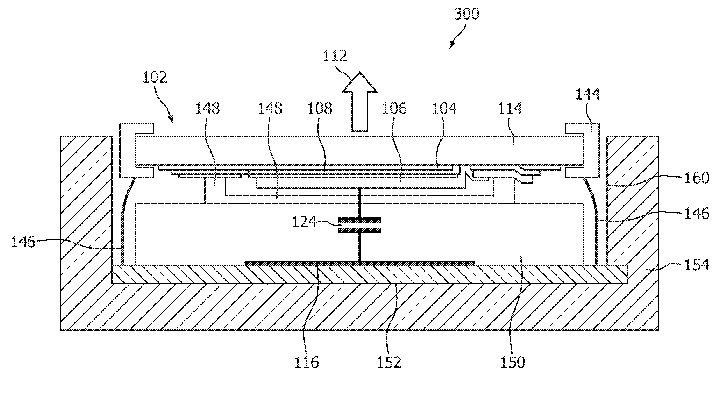
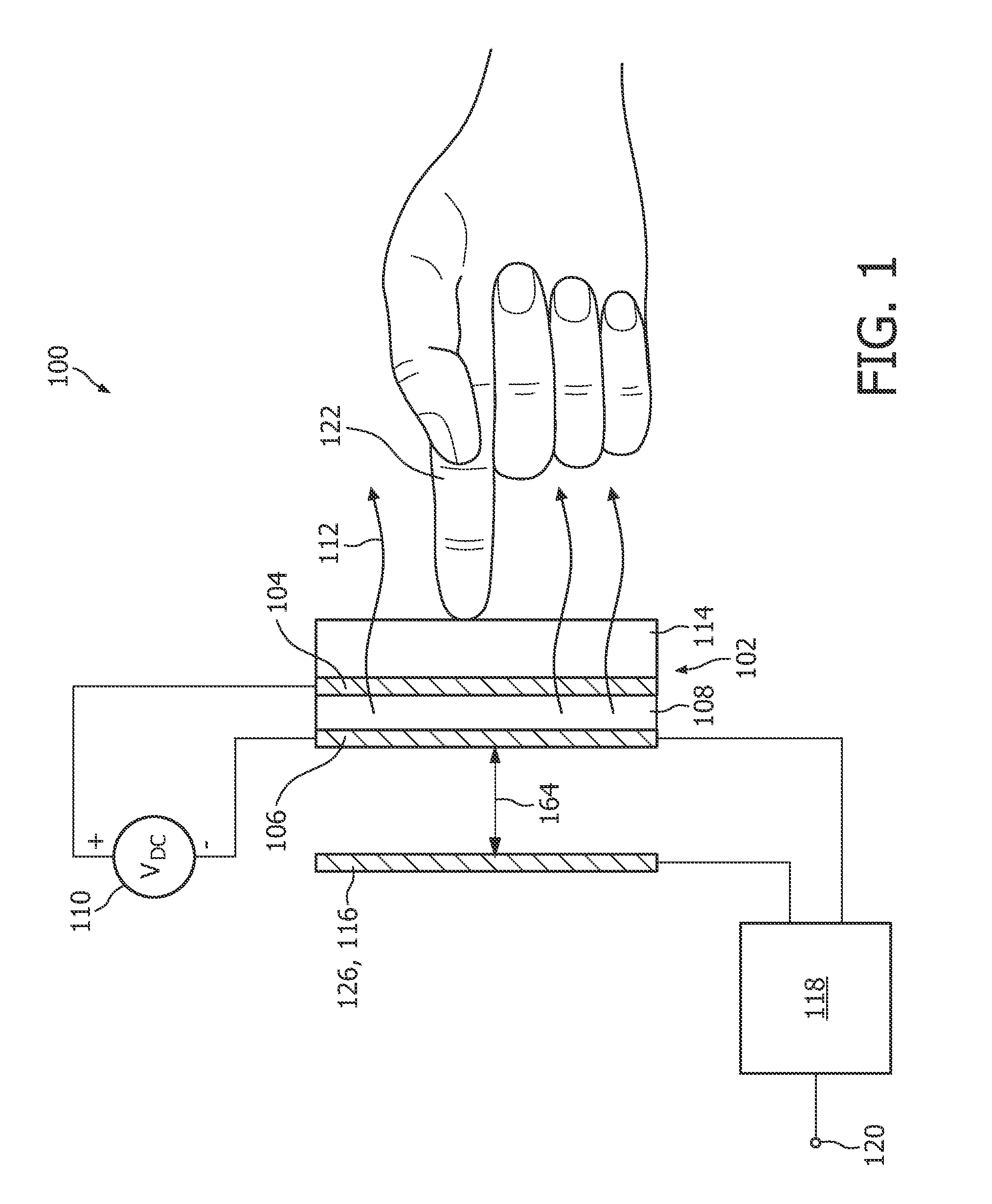
[0029]FIG. 1 is a functional schematic showing an embodiment of an OLED device 100 that functions by measuring the capacitance between the OLED means 102 and a conductive element 116. The OLED means is comprised of an anode 104, a cathode 106, an organic emissive layer 108 and a substrate 114. The OLED means is activated by providing a voltage source 110. When it is activated, light 112 is emitted from the organic layer 108. The cathode 106 is connected in this embodiment to the negative portion of a DC power supply 110 and the anode 104 is connected to the positive terminal on the ADC power supply 110. A capacitive sensor 118 is connected to a conductive element 116 and in this embodiment to the cathode 106.

[0030]The finger of an operator 122 operates th...


PUM


Abstract

An OLED device comprised of: an OLED means, a capacitive proximity sensing means for sensing a change in a capacitance, a mechanical element, and a means to provide a signal, wherein the OLED means and the mechanical element are movable relative to each other upon operation by a user and can assume a first position or a second position, wherein the capacitance is adapted to change between a first capacitance and a second capacitance when the OLED means and mechanical element are moved between the first position and the second position by an operator, and wherein the signal depends upon the capacitance.

Description

FIELD OF THE INVENTION[0001]This invention relates to organic light emitting diodes, and in particular to the integration of organic light emitting diodes and capacitive proximity sensors.BACKGROUND OF THE INVENTION[0002]Organic Light Emitting diodes (OLED) devices are comprised of two electrodes and an organic light emitting layer. The organic layer is disposed between the two electrodes. One electrode is the anode and the other electrode is the cathode. The organic layer is structured such that when the anode has a voltage bias that is sufficiently positive relative to the cathode, holes are injected from the anode and electrons are injected from the cathode. The necessary voltage bias depends upon the materials used for the organic layers. The holes and electrons recombine within the organic layer to induce an exited state in a molecule comprising the organic layer. Light is emitted during the process of excited molecules relaxing to their ground state. The anode is typically man...

Claims


Application Information

Patent Timeline
Patent Type & Authority Applications(United States)
IPC IPC(8): G09G3/14G06F3/045
CPCH03K17/962H03K2217/96062H03K2217/960785H03K2217/96076H03K2217/960755H03K2217/960795H10K71/00
Inventor HENTE, DIRK
Owner KONINKLIJKE PHILIPS ELECTRONICS NV
Why Eureka
Try Eureka