Recording apparatus and recording system

Active Publication Date: 2011-06-23
CANON KK
View PDF5 Cites 8 Cited by
  • Summary
  • Abstract
  • Description
  • Claims
  • Application Information

AI Technical Summary

Benefits of technology

[0027]According to an aspect of the present invention, a recording apparatus includes a recording unit configured to record an image on a recording medium using a recording head in which a first recording element array including a plurality of recording elements aligned along a predetermined direction and a second recording element array including a plurality of recording elements aligned along the predetermined direction, are arranged to be displaced in the predetermined direction so that there is an overlapping portion formed by an end of the first recording element array and an end of the second recording element array overlapping along a direction perpendicular to the predetermined direction, a first distribution unit configured to distribute test pattern data to a first recording element array and a second recording element array in the overlapping portion, a

Problems solved by technology

However, the overlapping portions of each of the chips may become slightly displaced due to the assembly error that occurs when manufacturing the overlapping head.
However, if there is an assembly error as illustrated in FIG. 3C, the colors generated by the non-overlapping portions and the overlapping portions become different.
Further, if a plurality of such pixels is collected together, a considerable difference between the colors becomes generated.
More specifically, when the recording head formed by connecting a plurality of the same color chips is used in recording as illustrated in FIG. 3D, a color deviation is generated due to the impact error.
The color deviation becomes visible as a streak of a different color on the recorded image and thus causes image degradation.
It thus becomes necessary to assemble the recording head chips with high precision to prevent generation of the color deviation, which increases cost.
However, when the discharge port distribution rate of the overlapp

Method used


Image

  • Recording apparatus and recording system
  • Recording apparatus and recording system
  • Recording apparatus and recording system

Examples


Embodiment Construction

[0048]Various exemplary embodiments, features, and aspects of the invention will be described in detail below with reference to the drawings.

[0049]

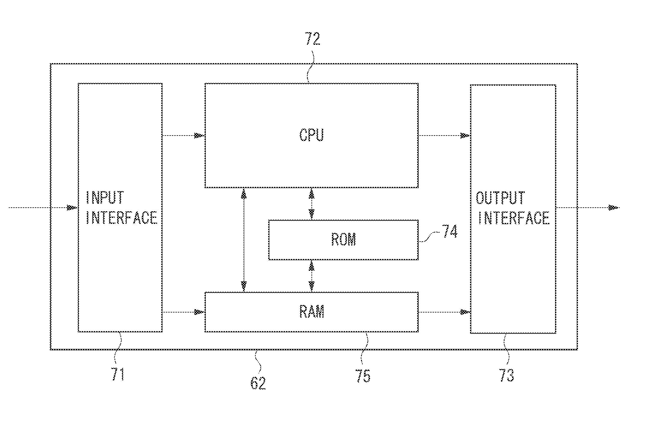
[0050]FIG. 5 is a schematic diagram illustrating an inkjet recording apparatus according to the present exemplary embodiment. Referring to FIG. 5, a head 60 includes ink containers 61 that contain inks, i.e., recording materials. A control circuit unit 62 includes a read-only memory (ROM) 74 and a random access memory (RAM) 75, i.e., storing units that are necessary when driving the head unit 60 as will be described below. The control circuit unit 62 also includes a central processing unit (CPU) 72, i.e., a calculation unit, and an interface, i.e., a communication unit.

[0051]The head 60 receives a recording signal and a control signal from the control circuit unit 62, and discharges ink from the discharge ports of a recording element (nozzles) based on the recording signal and according to the control signal. A conveyance roller (not illu...


PUM


Abstract

When a gradation mask is used to distribute image data to be recorded by overlapping portions in an overlapping head, color unevenness is generated in an image recorded by the overlapping portions due to a displacement in impact positions caused by an assembly error. As a result, accurate colorimetric measurement of patches recorded by the overlapping portion cannot be performed. To solve such a problem, a distribution ratio by which the image data is distributed to the overlapping portions is set to be approximately constant when recording a test pattern for performing color correction, as compared to when normally recording the image.

Description

BACKGROUND OF THE INVENTION[0001]1. Field of the Invention[0002]The present invention relates to a recording apparatus and a recording system that uses an overlapping head in which a plurality of recording heads is arranged to overlap with one another. In particular, the present invention relates to a recording apparatus and a recording system that performs color correction by performing colorimetric measurement of a test pattern.[0003]2. Description of the Related Art[0004]Image recording apparatuses such as a printer use various recording methods. In particular, a printer using an inkjet recording method can be widely applied to consumer products and to large size recording printers for industrial use. In general, an inkjet recording apparatus discharges ink from a recording head including a discharge port array formed of a plurality of discharge ports, and records an image on a recording medium.[0005]Along with the wide spread use of such inkjet recording apparatuses, there are p...

Claims


Application Information

Patent Timeline
IPC IPC(8): B41J29/38
CPCB41J2/2132
Inventor MOCHIZUKI, YUGOYAMADA, AKITOSHIGOTO, FUMITAKAISHIKAWA, TOMOKAZUNAKAMURA, TAKASHITSUCHIYA, OKINORINAKATANI, AKIHIKOONO, MITSUHIROSANO, AYUMIFUJITA, TAKASHIKAGAWA, HIDETSUGUGOTO, FUMIHIRO
Owner CANON KK
Why Eureka
Try Eureka