Ceramic-metal bonded body and method of producing the same

a technology of ceramic metal and bonded body, which is applied in the direction of metal layered products, pipe joints, electrical equipment, etc., can solve the problems of reducing the temperature uniformity of a wafer subjected to suction, and affecting the quality of the produ

Active Publication Date: 2013-01-29
NGK INSULATORS LTD
View PDF9 Cites 4 Cited by
  • Summary
  • Abstract
  • Description
  • Claims
  • Application Information

AI Technical Summary

Benefits of technology

[0008]The present invention has been made in order to solve the above problems, and a main object of the present invention is to prevent a decrease in the contact area and variations in the bonding performance between a plate and a supporting base of a ceramic-metal bonded body.
[0009]The present invention is directed to a method of producing a ceramic-metal bonded body by bonding a ceramic plate to a metal supporting base with a bonding sheet containing a resin as a main component, the method including a pre-bake step of heating the bonding sheet in air, in an inert gas, or in a vacuum in advance to reduce the amount of volatile components in the bonding sheet; and a bonding step of bonding the plate to the supporting base with the bonding sheet therebetween by placing the plate, the supporting base, and the bonding sheet in an airtight bag, reducing pressure in the airtight bag, and performing heating at a temperature lower than that of the pre-bake step while applying a pressure in an autoclave.
[0012]In the method of producing a ceramic-metal bonded body according to the present invention, in the pre-bake step, the bonding sheet may be applied onto the supporting base, and the supporting base to which the bonding sheet is applied may be heated to reduce the amount of volatile components in the bonding sheet. Alternatively, the bonding sheet may be applied onto the plate, and the plate to which the bonding sheet is applied may be heated to reduce the amount of volatile components in the bonding sheet. In this case, the producion method of the present invention can be performed without using a new jig.
[0013]In the method of producing a ceramic-metal bonded body according to the present invention, in the pre-bake step, a frame which is a board having an opening having the same shape as the bonding sheet of the ceramic-metal bonded body and a large-size sheet which is formed into the bonding sheet may be prepared, the large-size sheet may be applied onto the frame so that the large-size sheet covers the opening of the frame, and the frame to which the large-size sheet is applied may be heated to reduce the amount of volatile components in the large-size sheet. In this case, the heating time in the pre-bake step can be shortened as compared with the case where the amount of volatile components is reduced by performing heating after the bonding sheet is applied onto the supporting base and the case where the amount of volatile components is reduced by performing heating after the bonding sheet is applied onto the plate. This is because the volatile components are volatilized from one surface of the sheet in the former two methods described above, whereas the volatile components are volatilized from both surfaces of the sheet in the latter method using the frame.
[0018]This ceramic-metal bonded body can be obtained by the method of producing a ceramic-metal bonded body according to the present invention. Since the amount of volatile components in the bonding sheet is reduced in the producion, the amount of change in the weight of the bonding sheet is very small even when the ceramic-metal bonded body is exposed to high temperatures.

Problems solved by technology

However, when the existing electrostatic chuck is used at a high temperature of 80° C. or higher, gas is generated from the bonding material, and thus bubbles are formed between the plate and the bonding material and between the supporting base and the bonding material.
These bubbles may decrease the contact area between the plate and the supporting base and cause variations in the bonding performance, thereby decreasing the temperature uniformity of a wafer subjected to suction.
Furthermore, in the case where a heater is buried in the plate so as to control the temperature of the wafer to be constant, the temperature control may become difficult because the amount of heat transfer is changed by the generation of such bubbles.
These problems also occur in components having structures similar to the electrostatic chuck, that is, ceramic-metal bonded bodies.

Method used


Image

  • Ceramic-metal bonded body and method of producing the same
  • Ceramic-metal bonded body and method of producing the same
  • Ceramic-metal bonded body and method of producing the same

Examples


example 1

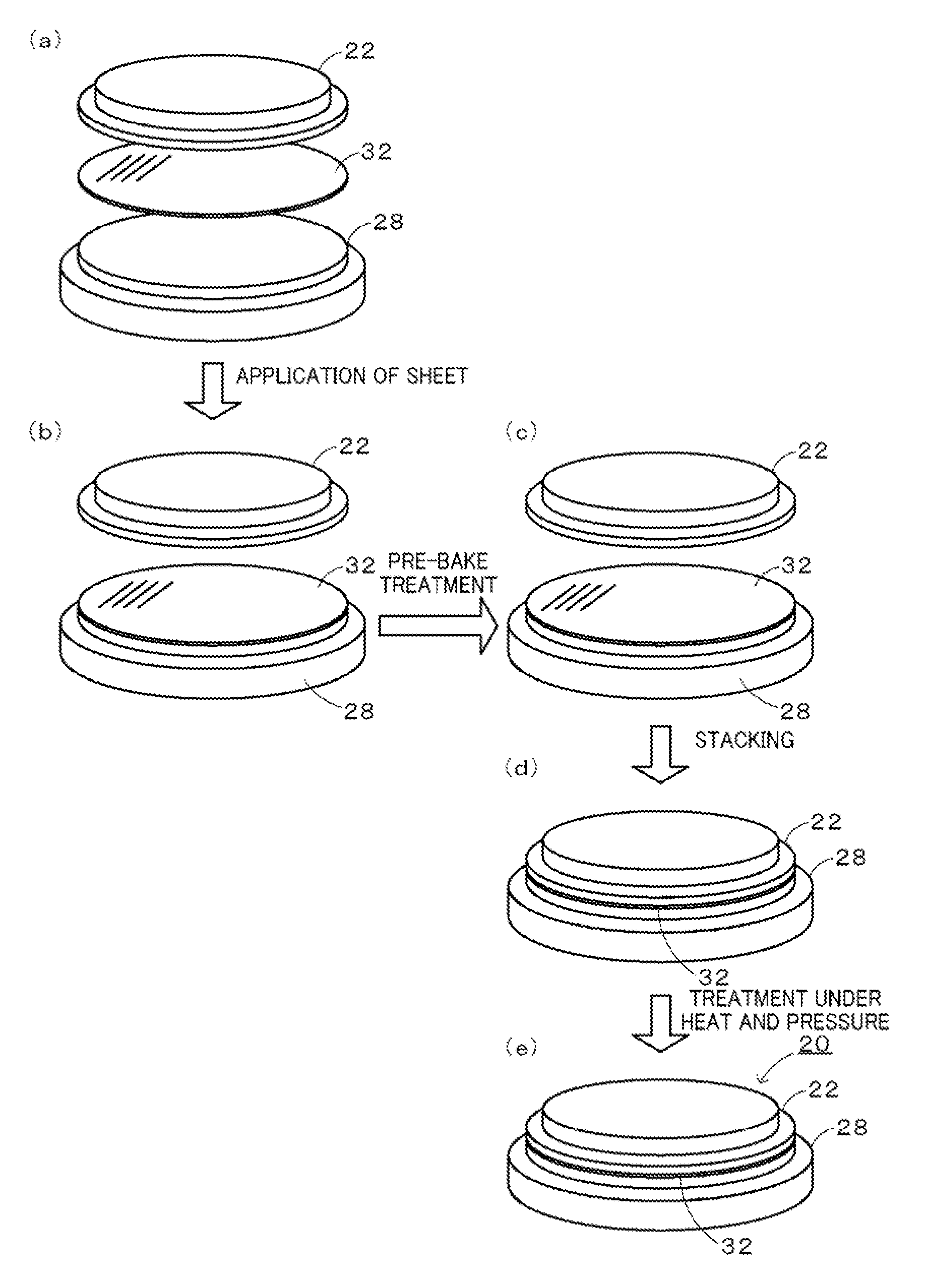
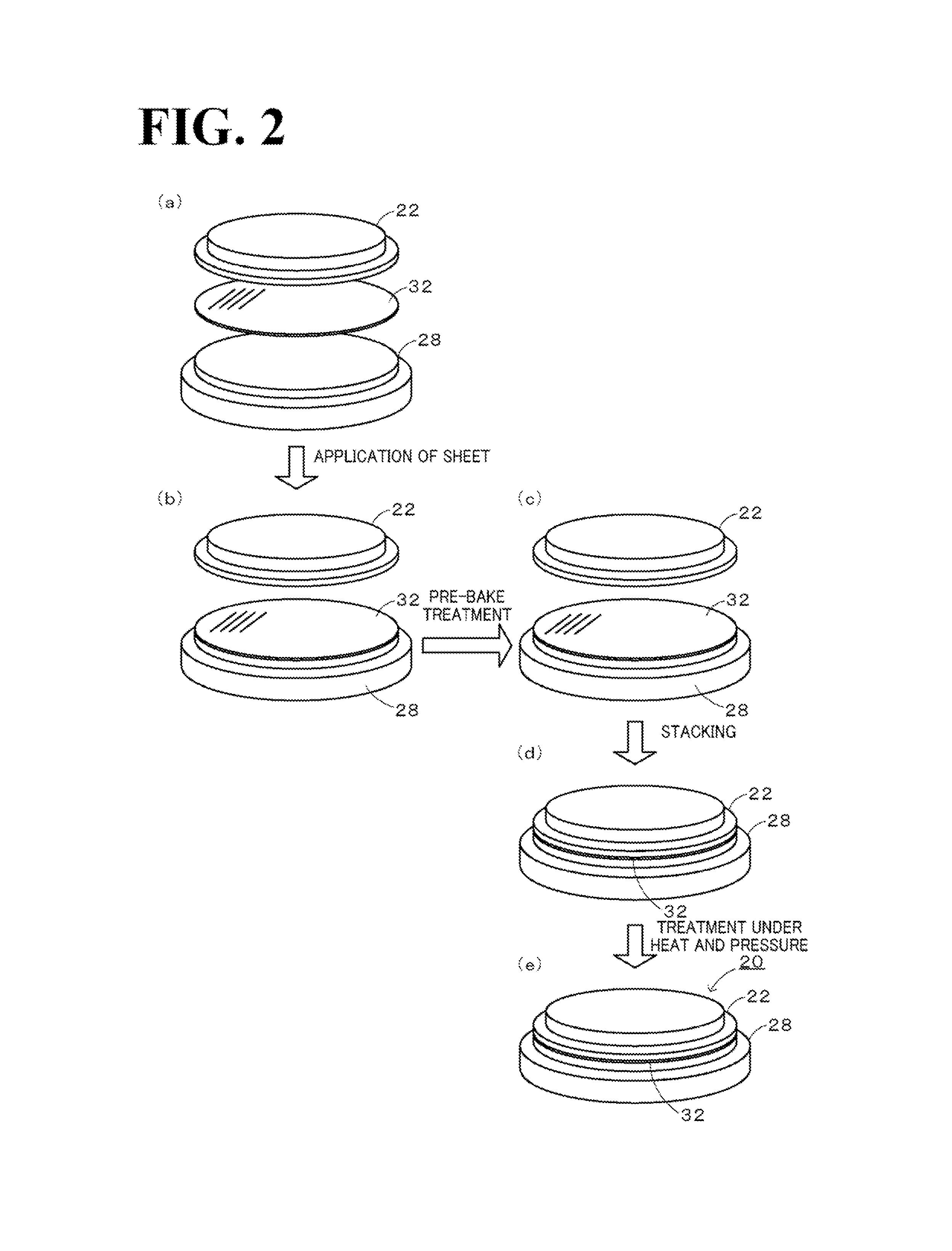
[0054]An electrostatic chuck in which an alumina plate 22 having a diameter φ of 297 mm and a thickness of 3 mm is bonded to an aluminum (Al) cooling plate 28 having a diameter φ of 297 mm and a thickness of 18 mm with an acrylic resin bonding sheet 32 having a thickness of 0.15 mm was produced as an example of an electrostatic chuck 20. This electrostatic chuck 20 was produced in accordance with the first producion method described above. Specifically, a bonding sheet 66 was applied onto the Al cooling plate 28, and a pre-bake treatment was then conducted. In the pre-bake treatment, the temperature was increased at a rate of 32° C. / h in a special furnace in which the pressure was reduced to 10 Pa or less. When the temperature reached 120° C., the temperature was controlled to be constant and maintained at 120° C. for 20 hours. The temperature was then decreased at a rate of 4° C. / h. The cooling plate 28 to which the bonding sheet 66 was applied was then bonded to the plate 22. Spec...

example 2

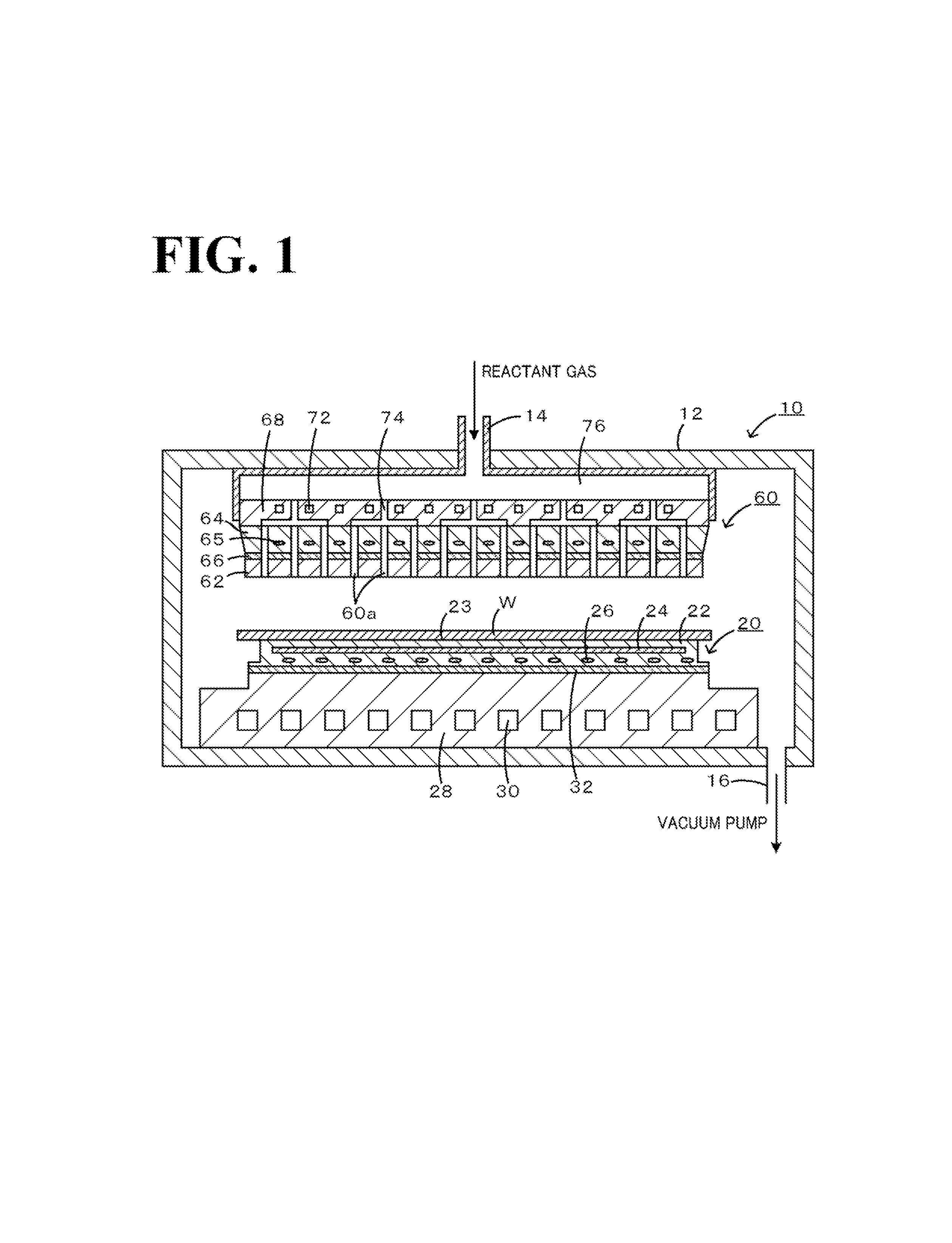
[0058]A showerhead including a silicon carbide (SiC) plate 62 having a diameter φ of 430 mm and a thickness of 4 mm and a metal electrode plate 64 composed of aluminum (Al), having a tapered outer circumference with a diameter φ of one surface of 430 mm and a diameter φ of another surface of 450 mm, and having a thickness of 20 mm, the plate 62 and the metal electrode plate 64 being bonded to each other with a silicone resin bonding sheet 66 having a thickness of 0.25 mm therebetween, was produced as an example of a showerhead 60. Small holes 60a each had a diameter φ of 0.1 mm, and the distance between adjacent small holes 60a was 4 mm. This showerhead 60 was produced in accordance with the second producion method described above. Specifically, the bonding sheet 66 was applied onto the SiC plate 62, and a pre-hake treatment was then conducted. In the pre-bake treatment, the temperature of the plate 62 was increased at a rate of 10° C. / h in a special furnace in which the pressure wa...


PUM

PropertyMeasurementUnit
temperatureaaaaaaaaaa
thicknessaaaaaaaaaa
pressureaaaaaaaaaa

Abstract

To form an electrostatic chuck, a bonding sheet is applied onto the upper surface of a cooling plate and then the cooling plate is placed in a vacuum dryer at a pressure of 2,000 Pa or less for a pre-bake treatment at 120° C. to 130° C. for 15 to 40 hours, followed by natural cooling. A plate is then stacked on the bonding sheet so that the lower surface of the plate is aligned with the upper surface of the bonding sheet, which is applied onto the cooling plate. The resulting stacked body is placed in a heat-resistant resin bag, and is then placed in an autoclave and treated together for several hours under pressure and heat.

Description

CROSS-REFERENCE TO RELATED APPLICATIONS[0001]This is a continuation of the International Application No. PCT / JP2010 / 052557 filed on Feb. 19, 2010.BACKGROUND OF THE INVENTION[0002]1. Field of the Invention[0003]The present invention relates to a ceramic-metal bonded body and a method of producing the same.[0004]2. Description of the Related Art[0005]An electrostatic chuck is a component used in an etching step which is one step of semiconductor manufacturing processing. More specifically, an electrostatic chuck is a component used for performing a uniform etching process on a silicon wafer by applying suction to the silicon wafer through a Johnsen-Rahbek force or a Coulomb force in a vacuum and uniformly cooling heat generated in etching. Examples of functions necessary for this component include (1) a vacuum holding power, (2) a responsiveness of applying suction to and releasing a silicon wafer, (3) a property for making the temperature of the entire surface of the silicon wafer su...

Claims


Application Information

Patent Timeline
Patent Type & Authority Patents(United States)
IPC IPC(8): B32B37/00B29C65/00
CPCC04B35/6269C04B37/028H01L21/67109H01L21/6831B32B15/04H01L21/6833C04B35/63424Y10T279/23C04B2235/656C04B2235/6567C04B2235/6581C04B2237/343C04B2237/346C04B2237/365C04B2237/366C04B2237/402C04B2237/525C04B2235/6562C04B2235/6565Y10T428/31678C04B37/02H01L21/683
Inventor AIHARA, YASUFUMISUGIMOTO, HIROYATANAKA, SHUNSUKEOHBA, KAZUMAWAKI, JYUNYA
Owner NGK INSULATORS LTD
Why Eureka
Try Eureka