Valves and other flow control in fluidic systems including microfluidic systems

a fluidic system and valve body technology, applied in the field of microfluidic systems, can solve the problems of large capital equipment, high cost, and/or complicated fabrication,

Active Publication Date: 2011-06-23
PRESIDENT & FELLOWS OF HARVARD COLLEGE
View PDF45 Cites 76 Cited by
  • Summary
  • Abstract
  • Description
  • Claims
  • Application Information

AI Technical Summary

Benefits of technology

[0007]In another embodiment, a microfluidic system includes a delivery channel having an upstream portion and a downstream portion, and a first channel section and a second channel section downstream of and fluidly connected to the delivery channel at a junction. The microfluidic system also includes a valve, downstream of the junction, associated with the first channel section, able to vary hydrodynami...

Problems solved by technology

These methods, however, typically require substantial capital eq...

Method used


Image

  • Valves and other flow control in fluidic systems including microfluidic systems
  • Valves and other flow control in fluidic systems including microfluidic systems
  • Valves and other flow control in fluidic systems including microfluidic systems

Examples


example 1

Control of Single-Layer (e.g., “Planar') Valves

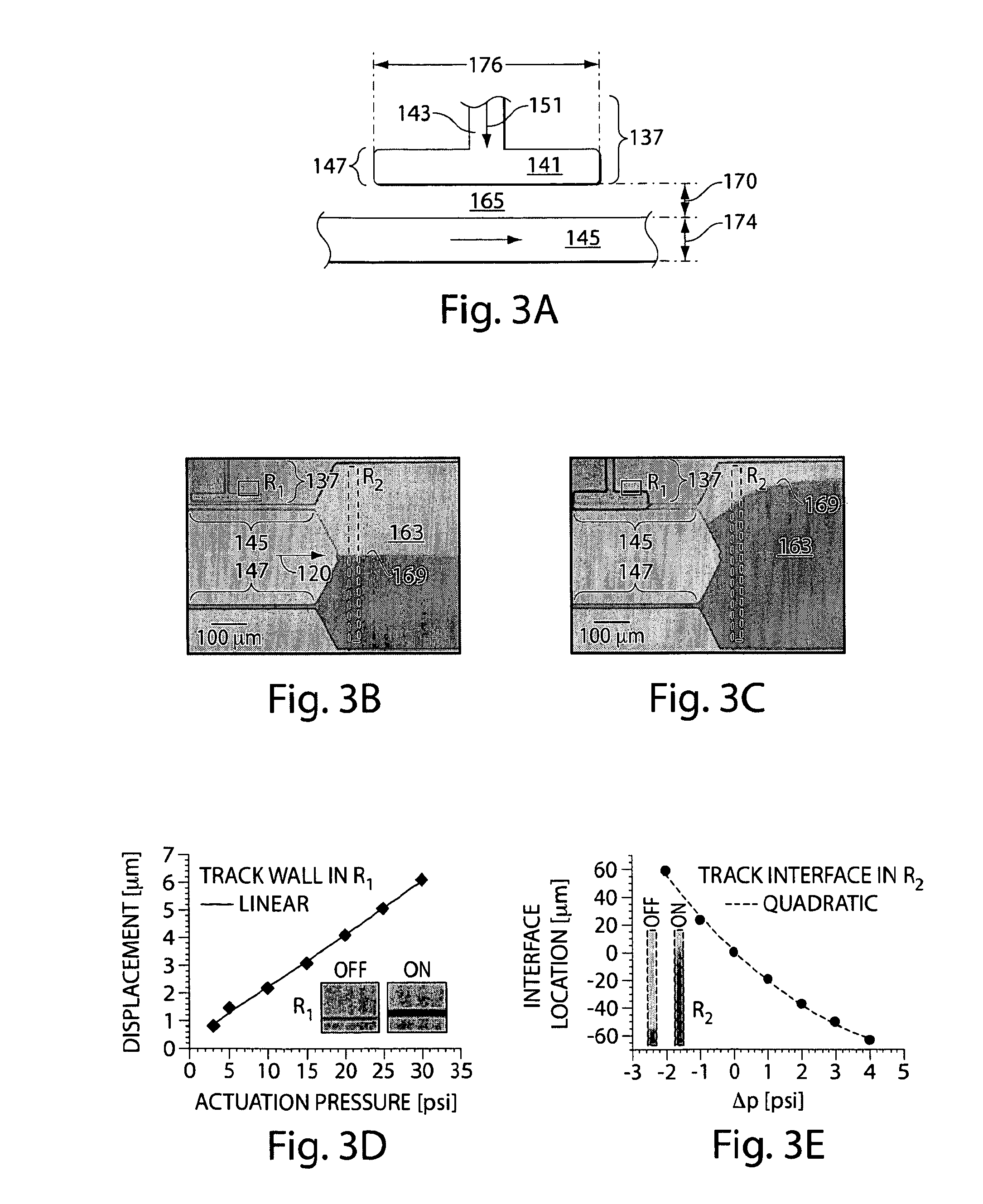
[0127]This example shows the control afforded by single-layer valves. FIG. 3A illustrates a top view of a single layer (e.g., “planar”) valve. To quantify the single-layer valve control, the pressure drop in the constricted channel was measured as a function of the actuation pressure applied to the valve channel. To measure the actuation pressure, fixed input pressure was applied to the fluid channel while varying the actuation pressure of the valve channel. This action deflected the elastic PDMS membrane, which was optically measured by tracking the wall in R1, as shown in FIGS. 3B-3C. This method provided measurements of the wall deflection as a function of the valve actuation pressure, which was used to calibrate the device. To extract a smooth calibration curve, the data were fit to a line, as shown in FIG. 3D. The calibration enabled the optical measurement of the pressure used to actuate the valve.

[0128]A microfluidic differential...

example 2

Performance of Single-Layer Valves

[0130]This example shows the effect of crosslinking density and channel dimensions on the pressure drop across a constricted channel as a function of the pressure used to actuate a valve constricting the channel.

[0131]Valves such as those shown in FIG. 3A-3C can control flow by constricting microchannels. The performance of a valve depends on the physical properties of both the valve and the channel to be deformed, which can be understood from the approximation for pressure-driven laminar flow in a high-aspect ratio channel: Δp∝vl / w3h; where Δp is the pressure drop along a microchannel (e.g., channel section 145 of FIG. 3A), v is the fluid flow rate, l is the channel length, w is the channel width, and h is the channel height, with w<

[0132]To determine the importance of the flexibility of a PDMS membrane (e.g., positioned between a control channel an...

example 3

Quantification of the Range and Precision of Rate Control Using Planar Valves

[0134]This example shows the operation of a continuous flow control microfluidic device in which the total flow rate through the device was 1000 μL / hr. To quantify the range and precision of flow rate control afforded by single-layer valves, the device shown in FIG. 5A was fabricated. The device included two parallel channels (e.g., channel section 182 and portions of channel section 184) that branch off from a delivery channel 181, with the flow rates along the channel sections being controlled using a valve 186. To use the device, the total flow rate through both channel sections was fixed at 1000 pL / hr using a syringe pump. When the valve was actuated, the flow rate in the channel section 182 was reduced while the flow rate in channel section 184 was increased. The velocity profiles for a sequence of actuation pressures was measured using Particle Imaging Velocimetry (Hy). For the PIV, 1 μm polystyrene t...


PUM


Abstract

Articles and methods for controlling flow in fluidic Systems, especially in microfluidic Systems, are provided. A microfluidic System includes a configuration such that the actuation of a single valve can allow the switching of fluids from a first fluid path (e.g., a first channel section) to a second fluid path (e.g., a second channel section). This may be achieved by incorporating a valve (38) with a first channel section (24), which may have a lower hydrodynamic resistance than a second channel section (28) prior to actuation of the valve. Actuation of the valve (38) can cause only the hydrodynamic resistance of the first channel section (24) to increase, thereby redirecting fluid flow into the second channel section (28) (which now has a relatively lower hydrodynamic resistance). The valve comprises a control channel (40) for introducing a positive or reduced pressure, and is adapted to modulate fluid flow in an adjacent channel section by constricting or expanding the channel section (24).

Description

GOVERNMENT FUNDING[0001]Research leading to various aspects of the present invention was sponsored, at least in part, by the NSF, under Grant Nos. DMR-0602684, DBI-0649865 and DMR-0213805. The U.S. Government has certain rights in the invention.FIELD OF INVENTION[0002]The present invention relates generally to articles and methods for controlling flow in fluidic systems, especially in microfluidic systems.BACKGROUND[0003]Fluidic systems, including microfluidic systems, have found application in a variety of fields. These systems that typically involve controlled fluid flow through one or more microfluidic channels can provide unique platforms useful in both research and production. For instance, one class of systems can be used for analyzing very small amounts of samples and reagents on chemical devices or “chips” that include very small fluid channels and small reaction / analysis chambers. Microfluidic systems are currently being developed for genetic analysis, clinical diagnostics,...

Claims


Application Information

Patent Timeline
IPC IPC(8): G01N1/10B01L3/00
CPCB01L3/0268B01L3/502738B01L3/502746B01L3/502784B01L2200/0605B01L2200/146Y10T436/2575B01L2300/0864B01L2300/0867B01L2400/0487B01L2400/0655B01L2400/082F16K99/0001B01L2300/0816B01L2200/0636F16K99/0017F16K99/0026F16K99/0055
Inventor ABATE, ADAM R.WEITZ, DAVID A.
Owner PRESIDENT & FELLOWS OF HARVARD COLLEGE
Why Eureka
Try Eureka