
Production of a device comprising magnetic structures formed on one and the same substrate and having respective different magnetization orientations

a technology of magnetic structure and substrate, which is applied in the manufacture/treatment of single device, galvano-magnetic device, magnetic recording, etc., can solve the problems of time-consuming implementation, difficult industrial use, and the inability to meet the requirements of the application

Active Publication Date: 2011-06-23
COMMISSARIAT A LENERGLE ATOMIQUE & AUX ENERGIES AKTERNATIV
View PDF4 Cites 26 Cited by
  • Summary
  • Abstract
  • Description
  • Claims
  • Application Information

AI Technical Summary

Benefits of technology

This may make it possible to block the magnetization of said layer of ferromagnetic material F in a defined direction during the ordering annealing.
The application of the magnetic field may make it possible to saturate the magnetization in each block and thus to prevent the appearance of magnetic domains.
This makes it possible to use magnetic blocks having respective magnetizations oriented at 90° to one another.

Problems solved by technology

The manufacture of a sensor comprising magnet zones having different magnetization orientations on one and the same substrate poses a problem.
The second approach may prove to be very time-consuming to implement when the number of magnetization zones to be created on the substrate is high, and is therefore difficult to use on an industrial scale.
The first approach has the disadvantage that it requires the use of different materials having sufficiently different annealing temperatures under a magnetic field, which limits the choice of materials and complicates the manufacturing process.
The problem addressed is that of finding a new method for producing, on one and the same substrate, zones having respective different and fixed magnetization orientations.

Method used


Image

  • Production of a device comprising magnetic structures formed on one and the same substrate and having respective different magnetization orientations
  • Production of a device comprising magnetic structures formed on one and the same substrate and having respective different magnetization orientations
  • Production of a device comprising magnetic structures formed on one and the same substrate and having respective different magnetization orientations

Examples


Embodiment Construction

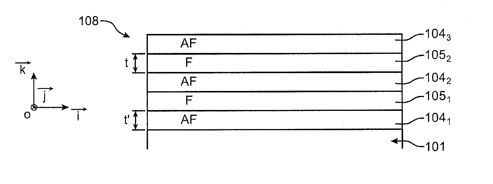
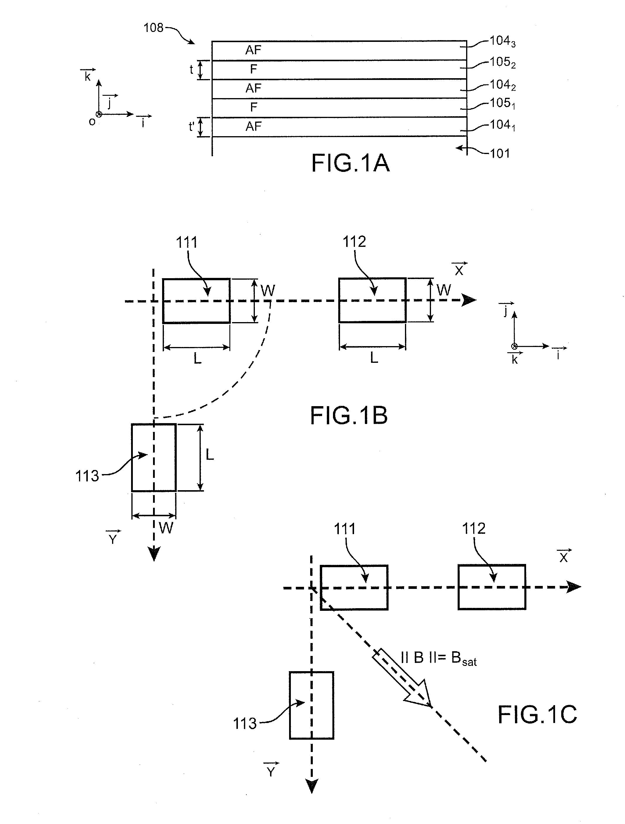
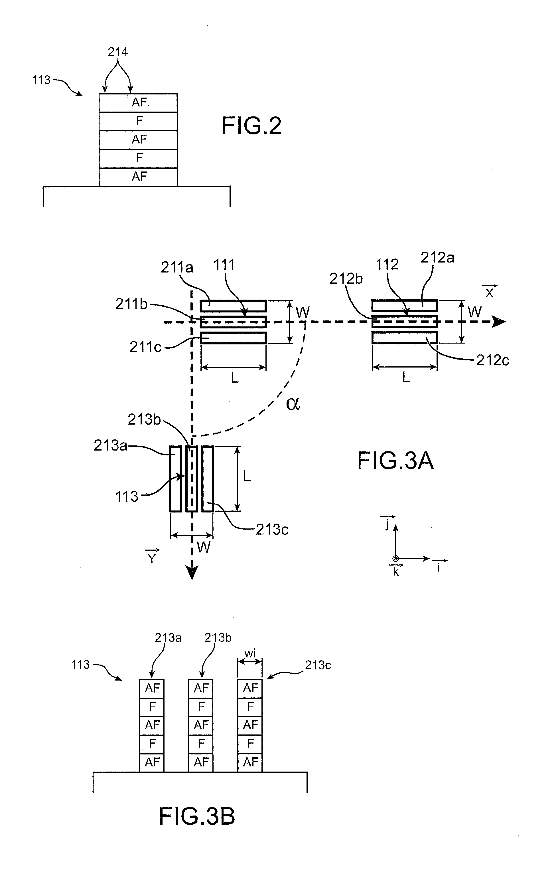
One example of a method for producing a device comprising, on one and the same substrate, zones of different magnetic orientations will now be given in connection with FIGS. 1A-1C, 2, 3A-3B.

The first step of this method, shown in FIG. 1, may consist in forming a stack of magnetic layers on a support 101, which may be for example a silicon layer of an SOI substrate (SOI denoting “silicon on insulator”).

The stack is formed of an alternating arrangement of layers 1041, . . . , 104m (where m is an integer for example equal to 3 in FIG. 1A) based on an antiferromagnetic material AF and layers 1051, . . . , 105n where n is an integer for example between 4 and 25 (in FIG. 1A, n is for example equal to 2) based on a ferromagnetic material F.

The ferromagnetic material F may be formed on the basis of a soft magnetic material, having a strong saturation magnetization Ms typically greater than 1000 emu / cm3. The ferromagnetic material F may be based for example on an alloy of Fe, Co and Ni.

The a...


PUM


Abstract

The invention relates to a method for producing a device comprising magnetic blocks magnetized in different directions, comprising steps of:a) forming, in a stack of one or more layers of at least one antiferromagnetic material and one or more layers of at least one ferromagnetic material resting on a substrate, at least one first block and at least one second block, said blocks being longilineal and separate and extending respectively in a first main direction and in a second main direction, the first and the second main direction forming between them a first non-zero angle α,b) annealing said blocks at a temperature greater than the ordering temperature of said antiferromagnetic material or than the blocking temperature or than the Néel temperature of said antiferromagnetic material.

Description

TECHNICAL FIELDThe invention relates to the field of devices equipped with a plurality of magnetized structures formed on a substrate, and provides an improved method for producing magnetic zones having respective magnetizations of different orientations on one and the same support.It finds applications in the field of devices for detecting and / or measuring a magnetic field, for example that of magnetic sensors of the MEMS (MEMS=Micro-electro-mechanical systems) or NEMS (NEMS=Nano-electro-mechanical systems) type, suitable for measuring magnetic fields along a plurality of axes, in particular along three axes.It applies for example to the production of devices for measuring the Earth's magnetic field, such as devices having a compass function.PRIOR ARTIt is known to produce a magnetic sensor capable of detecting a magnetic field along 3 axes.To do this, it proves necessary to create zones forming a magnet, having directions of magnetization that are orthogonal to one another.The man...

Claims


Application Information

Patent Timeline
IPC IPC(8): H01L43/12
CPCB82Y25/00Y10T428/1143G01R33/093G01R33/0052
Inventor REDON, OLIVIER
Owner COMMISSARIAT A LENERGLE ATOMIQUE & AUX ENERGIES AKTERNATIV
Learn More