
Sport racquet

a manufacturing method and technology for sports racquets, applied in the field of sports racquets, can solve the problems of weakening the molded frame, high production cost, and higher purchasing cost of the final consumer,

Inactive Publication Date: 2011-06-23
GAZZARA ROBERT +3
View PDF14 Cites 5 Cited by
  • Summary
  • Abstract
  • Description
  • Claims
  • Application Information

AI Technical Summary

Benefits of technology

[0008]The overall object of the present invention is to provide an improved method of manufacturing a racquet frame, one or more portions of which comprise port string holes are formed from a single frame tube.
[0009]Within this overall object, it is a particular object of the present invention to provide an improved method of manufacturing a racquet frame, in which port string holes are formed avoiding those post-curing operations, such as drilling, which may weaken the racquet frame after the racquet frame is molded.
[0010]A further object of the present invention is to provide an improved method of manufacturing a racquet frame, which allows molding together frame regions made of different materials, particularly in the vicinity of the string port holes.
[0011]It is also an object of the present invention is to provide an improved method of manufacturing a racquet frame, which is easy to carry out at relatively low cost.

Problems solved by technology

Although such a manufacturing method has shown to be quite effective in the manufacturing of high quality racquet frames with string port holes, it has been seen that production costs are relatively high.
This fact necessarily entails higher purchasing costs for the final consumer and / or lower margins for the provider.
However, drilling holes, particularly drilling large holes such as the string port holes, is a kind of post-curing operation on the molded racquet frame, which may weaken the molded frame, given the fact that the frame fibers are broken.
Unfortunately, these solutions have shown to be quite complicated to be carried out on industrial large-scale manufacturing processes and to entail relatively high production costs.

Method used


Image

  • Sport racquet
  • Sport racquet
  • Sport racquet

Examples


Embodiment Construction

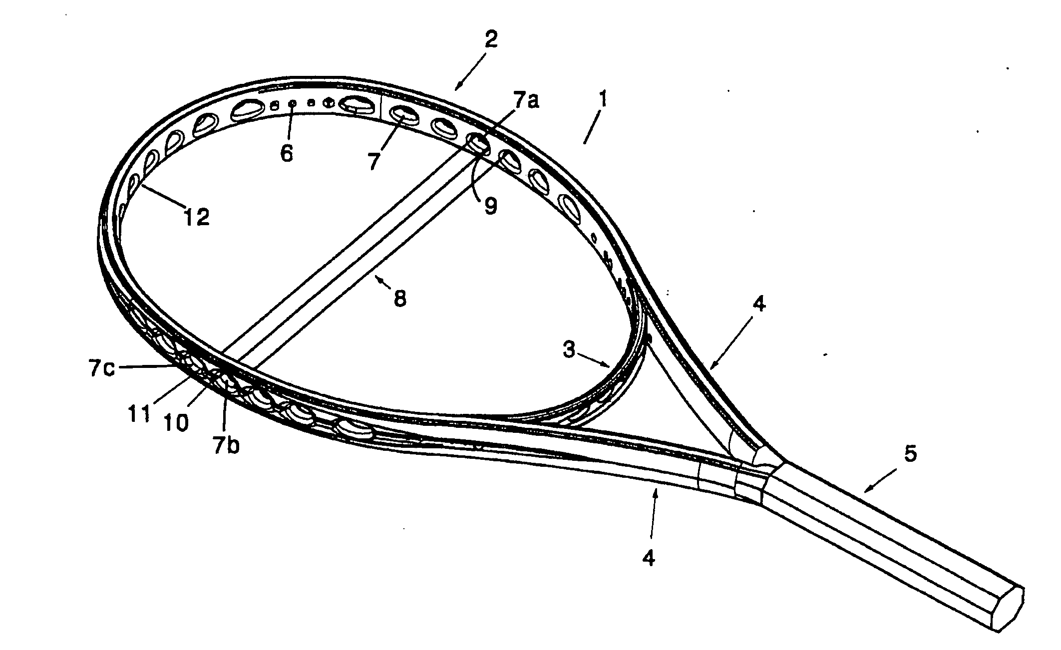
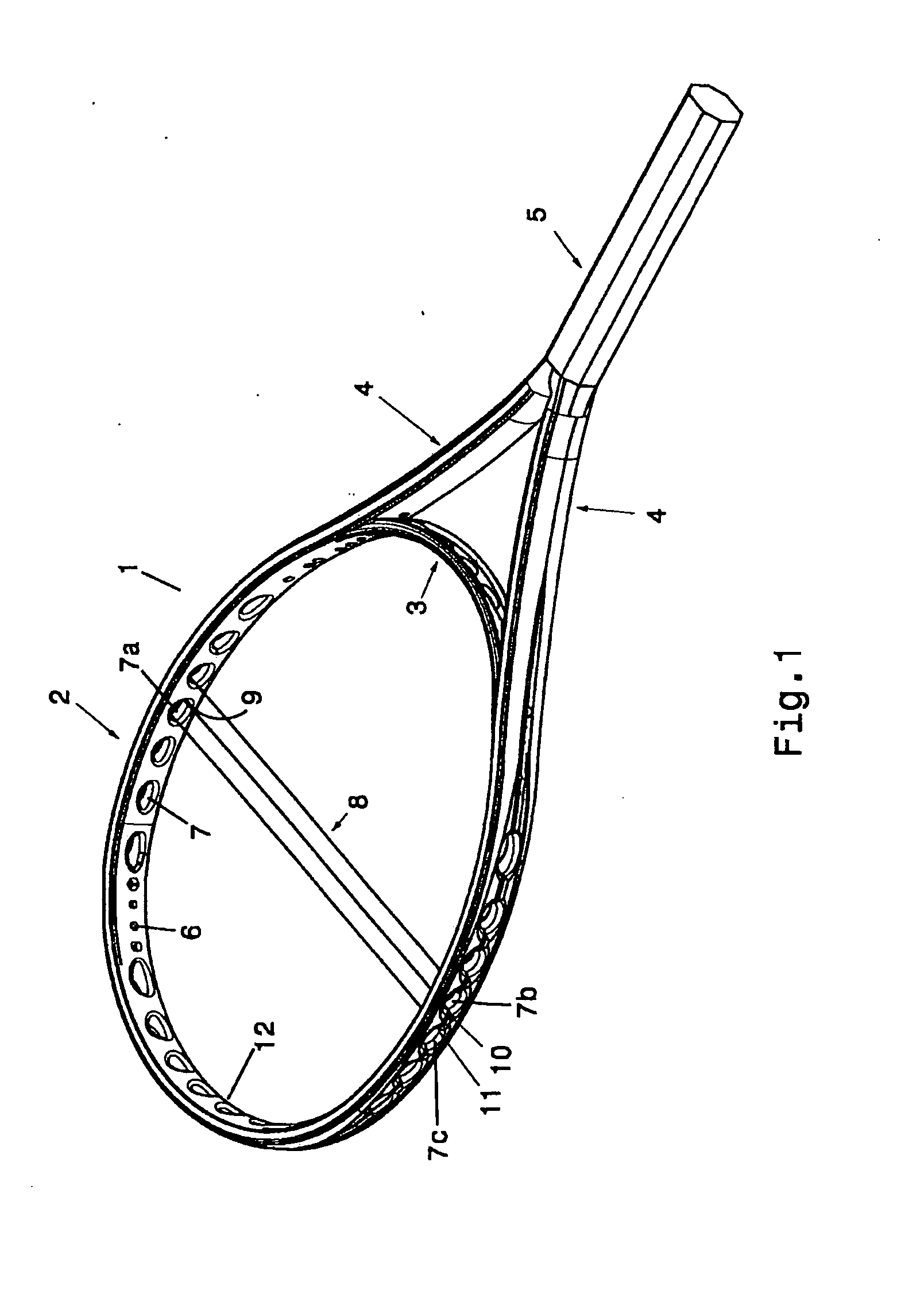
[0031]Referring to FIG. 1, it is shown a tennis racquet frame 1 manufactured with the method according to the present invention. The frame 1 includes a head portion 2, which includes a throat bridge 3 and a tip 12, a pair of converging shafts 4, and a handle portion 5. The head portion 2 includes a plurality of conventional string holes 6 and a plurality of consecutive port string holes 7. A handle (not shown) is mounted on the handle portion 5, and thereafter the handle may be wrapped with a grip.

[0032]As described in greater detail in WO 2004 / 075996, which is incorporated herein by reference, string port holes 7 on opposite sides of the head 2, as well as opposed port string holes in the tip 12 and throat bridge 3, are offset relative to one another. In this manner, e.g., along the sides, a string segment 8, which bears against the lower bearing surface 9 of one port string hole 7a, after crossing the string bed, bears against the upper bearing surface 10 of the string port hole 7...


PUM

PropertyMeasurementUnit
shapeaaaaaaaaaa
moldableaaaaaaaaaa
perimeteraaaaaaaaaa

Abstract

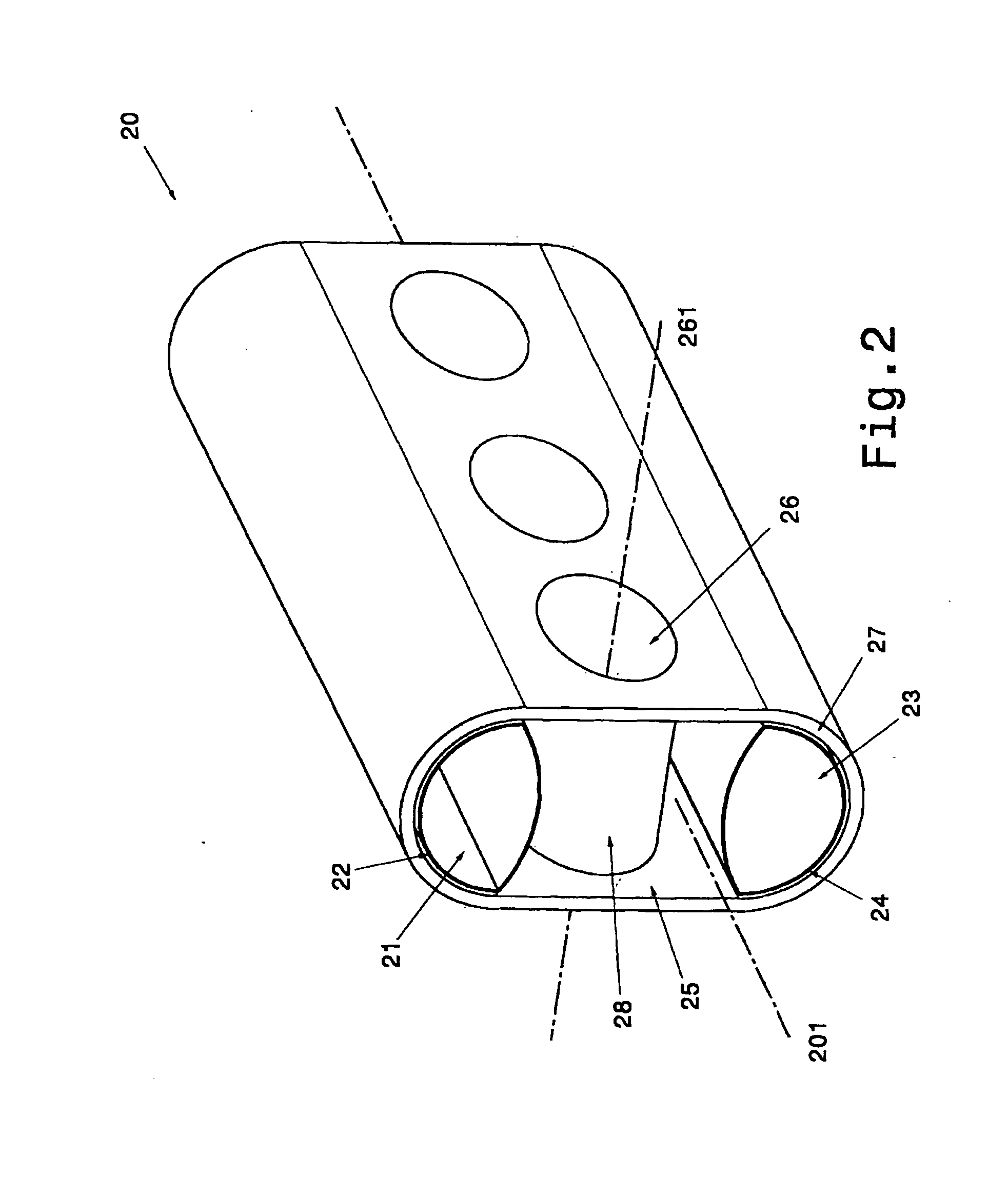
The present invention relates to a method for manufacturing at least a portion of a sports racquet frame that comprises a step a) of providing a moldable tube structure containing a first inflatable bladder and a second inflatable bladder. The first and second inflatable bladders are positioned on opposite first and second regions of the moldable tube structure. At an intermediate region, the tube structure comprises one or more cross channels, which pass through the moldable tube structure. The method according to the present invention comprises also a further step b) of inserting said tube structure inside a mold forming a mold cavity of a desired shape. Mold members are inserted into the cross channels of the tube structure, so that the outer surface of the mold member faces the inner surface of the corresponding cross channel. The mold members have position and orientation that correspond to the position and orientation, along the string bed plane, of the string port holes, which are to be formed on said frame portion. The method, according to the present invention, comprises also a step c) of pressurizing the first and second bladders, so that the tube structure conforms to the shape of the mold, and heating the mold, so that the tube structure cures. The method, according to the present invention, comprises a further step d) of removing the cured tube structure from the mold cavity and removing the mold members from the cross channels.

Description

CROSS-REFERENCE TO RELATED APPLICATIONS[0001]The present invention is a divisional of U.S. application Ser. No. 11 / 707,845, filed on Feb. 15, 2007.BACKGROUND[0002]The present invention relates to a method for manufacturing a sports racquet and a sports racquet obtained by said method, which may be, for example a tennis, squash, badminton, or racquetball racquet. More particularly, the present invention relates to an improved method for manufacturing a sports racquet comprising a racquet frame formed by a single tube and provided with enlarged string port holes therein.[0003]Sports racquets have a head portion containing an interwoven string bed, a handle, and a shaft portion connecting the head portion to the handle.[0004]In conventional racquets, holes for anchoring the ends of the strings are formed in the frame by drilling small string holes in the frame after the racquet is molded. Generally, each string hole accommodates a single string. Plastic grommet pegs, which are formed o...

Claims


Application Information

Patent Timeline
Patent Type & Authority Applications(United States)
IPC IPC(8): A63B49/10B28B7/32
CPCA63B49/002A63B49/007A63B49/106A63B51/00A63B51/10B29L2031/5245A63B2209/023B29C33/0016B29C33/505B29C70/342B29C70/865A63B2049/103A63B49/11A63B49/022A63B49/028
Inventor GAZZARA, ROBERTPINAFFO, MAUROPOZZOBON, MICHELPEZZATO, MAURO
Owner GAZZARA ROBERT
Learn More