Operating noise control device and operating noise control method for vehicle

a technology of operating noise and control device, which is applied in the direction of electric devices, process and machine control, instruments, etc., can solve the problem that the driver may not want sustained quiet operation, and achieve the effect of improving the noise of operation

Active Publication Date: 2011-06-23
NISSAN MOTOR CO LTD +1
View PDF11 Cites 10 Cited by
  • Summary
  • Abstract
  • Description
  • Claims
  • Application Information

AI Technical Summary

Benefits of technology

[0007]It is therefore an object of this invention to achieve an improvement with regard to the operating noise occurring during acceleration of a vehicle that uses an electric motor as a motive force source.
[0008]In order to achieve the object described above, an operating noise control device according to this invention, which controls operating noise in the vehicle with an electric motor used as a motive power source, includes a beat noise generating system that creates beat noise during vehicle acceleration by generating operating noise c...

Problems solved by technology

However, in certain situations the dr...

Method used


Image

  • Operating noise control device and operating noise control method for vehicle
  • Operating noise control device and operating noise control method for vehicle
  • Operating noise control device and operating noise control method for vehicle

Examples


first embodiment

[0040]Referring to FIGS. 1 and 2, FIGS. 3A and 3B, FIGS. 4A-4C, FIG. 5, FIGS. 6A and 6B, FIGS. 7A and 7B, FIGS. 8A and 8B and FIG. 9 of the drawings, this invention will be described.

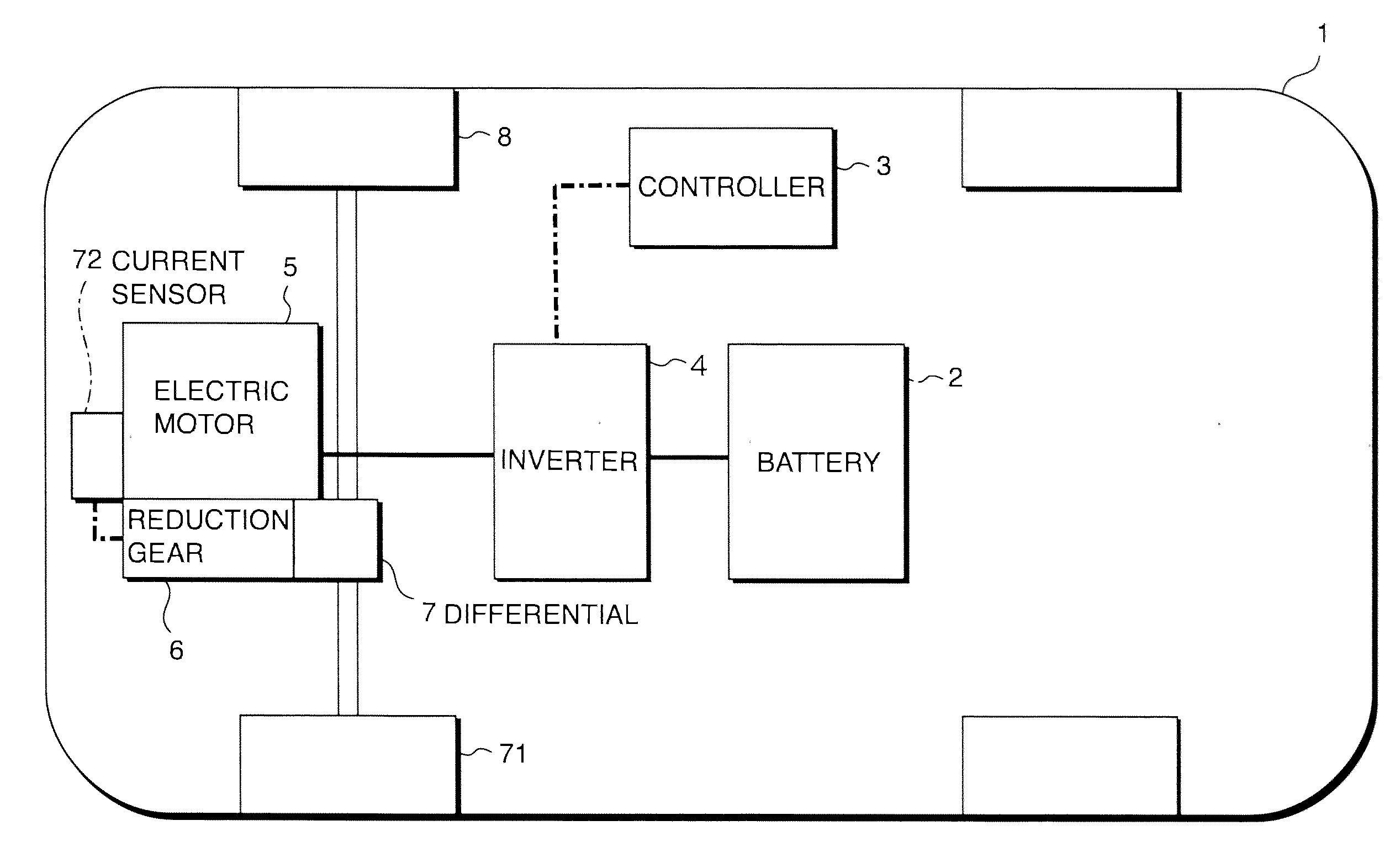
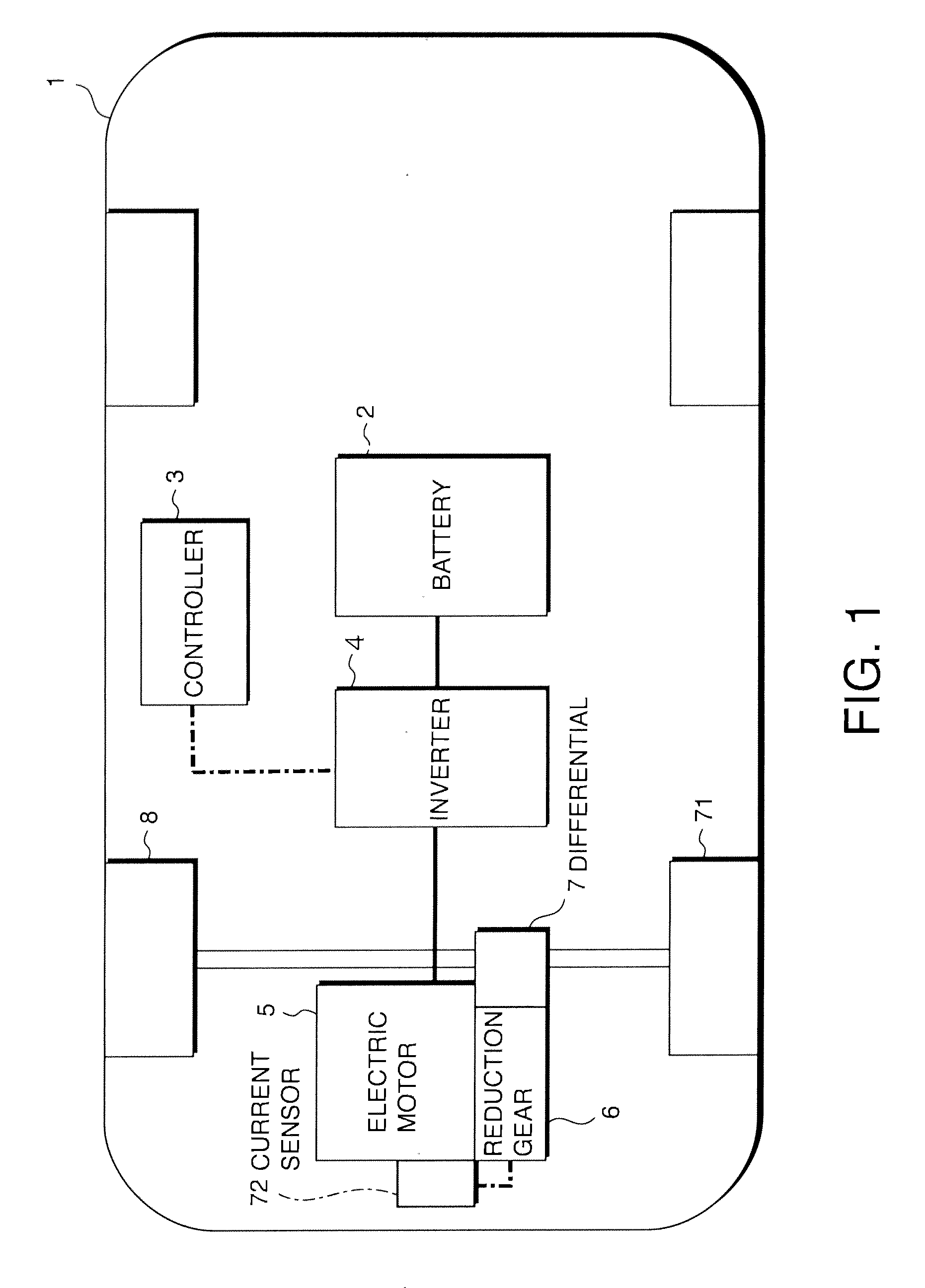
[0041]Referring to FIG. 1, a vehicle 1 equipped with an operating noise control device according to this invention travels as drive wheels are rotationally driven by an electric motor 5 with electric power supplied from a battery 2. Power is stored in the battery 2 in advance by supplying electric power from an external source.

[0042]DC power supplied from the battery 2 is first converted to three-phase AC power at an inverter 4 and thus is input as three-phase AC power to the electric motor 5. The electric motor 5 is constituted with a synchronous AC motor. The rotation of the electric motor 5 is transmitted to drive wheels 8 via a reduction gear 6 and a differential 7. The inverter 4 converts the electrical current based upon a command signal issued by a controller 3.

[0043]The controller 3 calculates d...

second embodiment

[0073]Referring to FIGS. 10A-10C, FIGS. 11A and 11B, FIGS. 12A-12C, FIGS. 13A-13C, FIGS. 14A and 14B and FIGS. 15A and 15B, this invention will be described.

[0074]This embodiment assumes a hardware configuration identical to that of the first embodiment and is distinguishable from the first embodiment only in the method adopted for higher-order component current application.

[0075]FIGS. 10A-10C indicate that the controller 3 in this embodiment controls the drive current for the electric motor 5 with current instruction values in FIG. 10C calculated by multiplying the basic current in FIG. 10A by a correction coefficient shown in FIG. 10B and defined in expression (4) below. A drive current corresponding to the current instruction values is then applied to the coils at the electric motor 5.

Kn=1+q·sin{(6+p)·θ+θn}  (4)

[0076]where, θn=2π(6+p)+θn-1;[0077]θ=electrical angle; and[0078]p, q,=coefficients determined in correspondence to the vehicle operating condition.

[0079]As expression (4) ...

third embodiment

[0090]Referring to FIG. 16, this invention will be described.

[0091]This embodiment is achieved by further adding an external operation panel 13 via which the driver is able to select any beat noise setting to the beat noise generation system in the second embodiment.

[0092]The external operation panel 13 is installed near the driver's seat in the vehicle 1. The external operation panel 13 includes a beat noise ON / OFF switch 14, a beat frequency adjustment dial 15, and a beat strength adjustment dial 16.

[0093]The beat ON / OFF switch 14 can be set to one of three positions, OFF, AUTO and MANUAL. The beat frequency adjustment dial 15 is operated when setting the coefficient p in Equation (4). The beat strength adjustment dial 16 is operated when setting the coefficient q in Equation (4).

[0094]If the driver selects the OFF position at the beat ON / OFF switch 14, the controller 3 does not add the higher-order component current to the drive current and thus, no beat noise is generated.

[0095]...


PUM


Abstract

A vehicle (1, 17) includes an electric drive motor (5, 19), an inverter (4) that provides a drive current to the electric motor (5, 19) and a controller (13) that controls the inverter (4). The controller (13) functions as a beat noise generation system that creates beat noise by generating a second operating noise containing a component an order of which is very close to a value representing an order of an operating noise generated in proportion to a rotation speed of the electric motor (5, 19) so as to create desirable traveling noise corresponding to an accelerating state while the vehicle accelerates.

Description

FIELD OF THE INVENTION[0001]This invention relates to control of motive power noise in a vehicle.BACKGROUND OF THE INVENTION[0002]JP2008-37133A published by the Japan Patent Office in the year 2008 proposes a beat noise preventing device that prevents beat noise in an electric vehicle that includes drive wheels each driven with an in-wheel motor equipped with an electric motor and a reduction gear.[0003]Beat noise occurs as operating noises originating from a plurality of in-wheel motors become superposed. Such beat noise is suppressed in the prior art by adjusting the frequency of the operating noise at the electric motor or the reduction gear in each wheel.SUMMARY OF THE INVENTION[0004]Assuring quiet operation has been generally considered to be a primary goal for a vehicle that uses an electric motor as the motive power source. However, in certain situations the driver may not want sustained quiet operation.[0005]The driver of a vehicle with an internal combustion engine used as ...

Claims


Application Information

Patent Timeline
IPC IPC(8): B60L9/18B60L11/18H02P27/06
CPCB60L3/00B60L11/18Y02T10/7005H02P29/0038Y02T10/642H02P27/06B60L50/50H02P29/50Y02T10/64Y02T10/70
Inventor ASAHARA, YASUYUKITOI, TAKESHIYOKOYAMA, KAZUKI
Owner NISSAN MOTOR CO LTD
Why Eureka
Try Eureka