
B1-mapping and b1l-shimming for MRI

a technology of mri and mapping, applied in the field of mri mapping and mapping, can solve the problems of reducing the examination time, reducing the mri sequence, and imposing the challenge of increasing the magnetic field strength used for clinical mri, so as to reduce the examination time, and improve the efficiency of workflow

Active Publication Date: 2011-06-30
KONINKLIJKE PHILIPS ELECTRONICS NV
View PDF12 Cites 50 Cited by
  • Summary
  • Abstract
  • Description
  • Claims
  • Application Information

AI Technical Summary

Benefits of technology

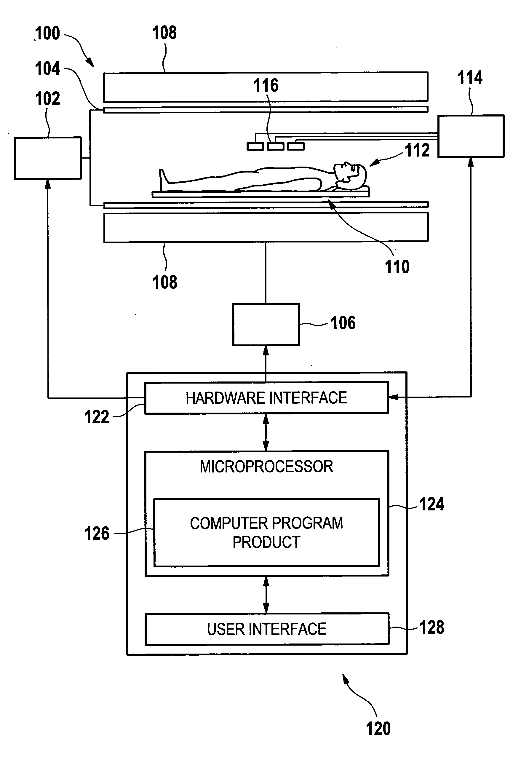
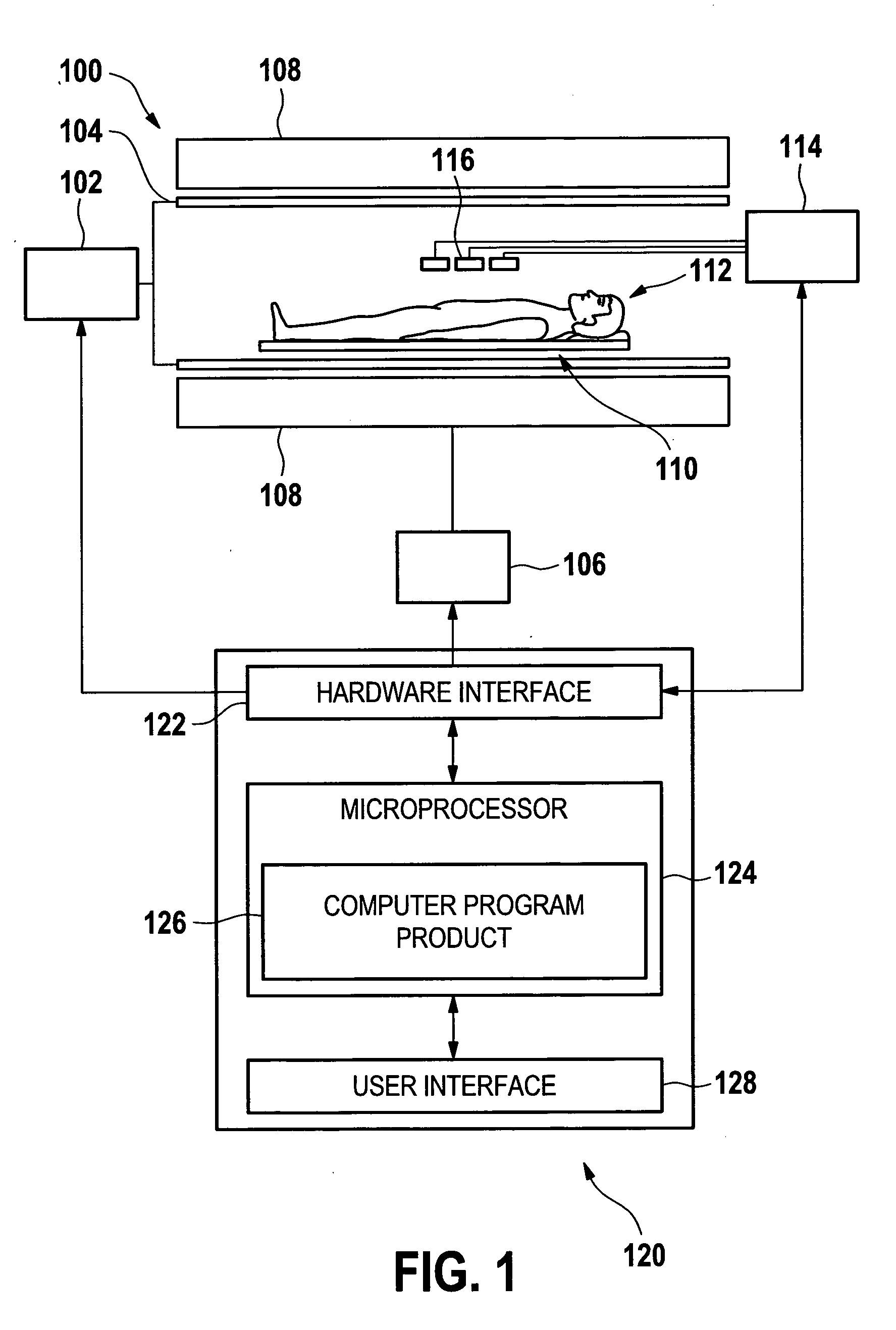
[0023]Embodiments of the invention provide for a fast and efficient way to minimize the increase in SAR caused by B1-shimming. Standard RF B1-shimming is typically performed by minimizing a cost function. These functions typically comprise the standard deviation of the resulting B1 map, and are solved using a non-linear, iterative search.
[0048]In accordance with an embodiment of the invention, a user interface could be designed which allows the operator to apply the B1 mapping to the acquisition of one or more separate MRI images. This has the advantage of increasing the workflow and saving time during an MRI examination.

Problems solved by technology

However, a technical challenge in increasing the magnetic field strength used for clinical MRI is imposed by the dielectric properties of the body.
The problem is that dielectric properties of the body cause the wavelength λ of the transmitted RF field (so-called B1 field) to become shorter, λ˜1 / B0.
This causes the local perturbations to the magnetic field induced by the transmitter coil to become non-uniform, resulting in non-uniform excitation, signal strength, and contrast in standard MRI sequences.
This can lead to errors in contrast of diagnostic images and to the possibility of a misdiagnosis.
This is impractical in a clinical setting, because the calculation of the electric fields requires extensive off-line modeling and calculations.
The B1-shimming of the individual volumes being imaged is not sufficient.
These techniques are seriously compromised by the B1 inhomogeneities present at high B0 fields.

Method used


Image

  • B1-mapping and b1l-shimming for MRI
  • B1-mapping and b1l-shimming for MRI
  • B1-mapping and b1l-shimming for MRI

Examples


example 1

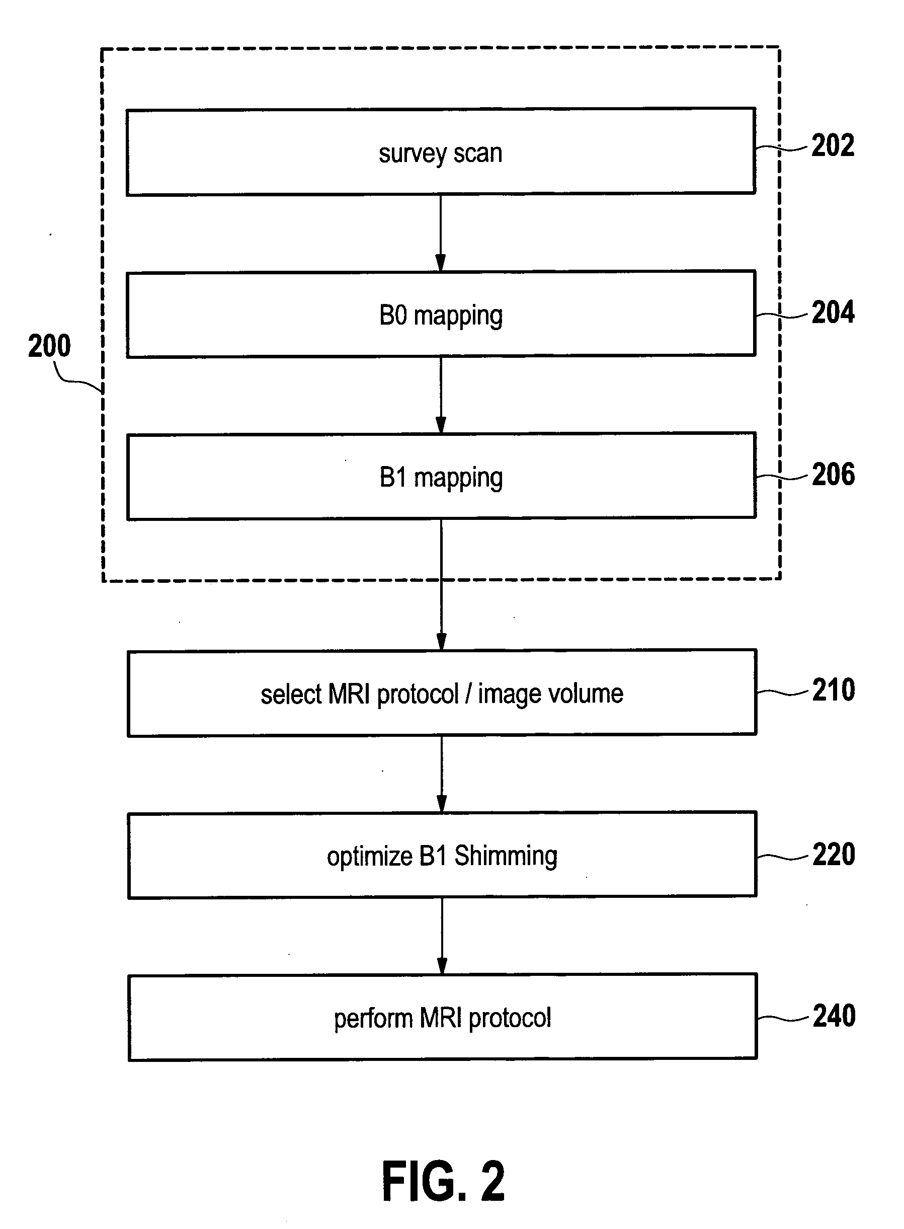
[0066]A liver examination is performed. As part of the preparation a low-resolution 3D volume B1 transmit mapping scan is performed to obtain the individual transmit coil sensitivities of a two-channel transmit system. For this purpose a 3D EPI accelerated scanning is performed using a modification of the approach described in Yarnykh. A portion of the modified pulse sequence diagram is shown in FIG. 3. The approach described in Yarnykh is modified by using EPI read-out pulses (334) to speed up 3D imaging. The volume of the B1 map needs to be much larger than the liver region. This is demonstrated by FIG. 4. Based on the acquired field maps, appropriate shimming coefficients for the RF objects of a specific MRI liver protocol are obtained. First the B1 homogeneity is optimized in a volume that corresponds to the FOV of a 3D gradient echo imaging scan that should be used in this example. This scan employs magnetization preparation. Thus, secondly for one of the magnetization preparat...

example 2

[0070]A pelvis examination is performed using local imaging. To image locally, a 3D RF pulse should be used to facilitate local signal excitation. This RF pulse has to be applied in an accelerated manner using an 8 element transmit system. A combined volume B1 and B0 mapping pre-scan is performed covering a larger volume than the one in that the actual scan will be performed. A parallel imaging-accelerated 3D gradient echo scan is used for mapping according to the Yarnykh approach. During the TR1 only a single echo is sampled, whereas during the long TR interval (TR2) an EPI-type read-out is performed, that samples the same profile several times after excitation. This allows performing chemical shift encoding to separate water and fat and to gain a B0 field map in a post-processing step. Based on the measured volume B1 maps the relevant coil sensitivities and the B0 inhomogeneity can be extracted to perform appropriate transmit SENSE RF pulse design. This is described in Katscher U,...


PUM


Abstract

The invention relates to a method of acquiring MRI image data comprising the following steps: performing a 3-dimensional B1 mapping of a first volume using a first voxel size, selecting an MRI protocol, performing the B1-shim in accordance with the MRI protocol, performing the MRI protocol to acquire MRI imaging data of a second volume using a second voxel size, wherein the first voxel size is larger than the second voxel size, wherein the first volume is larger than the second volume, and wherein the second volume is contained within the first volume.

Description

TECHNICAL FIELD[0001]The invention relates to a method, an apparatus, and a computer program product for performing an integrated B1-shimming of a Magnetic Resonance Imaging (MRI) system.BACKGROUND AND RELATED ART[0002]A static magnetic field is used by MRI scanners to align the nuclear spins of atoms as part of the procedure for producing images within the body of a patient. This static magnetic field is referred to as the B0 field. It is commonly known that increasing the strength of the B0 field used for performing an MRI scan offers the opportunity of increasing the spatial resolution and contrast resolution of the diagnostics images. This increase in resolution and contrast benefits physicians using an MRI image to diagnose a patient.[0003]During an MRI scan, Radio Frequency (RF) pulses generated by a transmitter coil cause perturbations to the local magnetic field, and RF signals emitted by the nuclear spins are detected by a receiver coil. These RF signals are used to constru...

Claims


Application Information

Patent Timeline
Patent Type & Authority Applications(United States)
IPC IPC(8): G01R33/34
CPCG01R33/246G01R33/3415G01R33/4838G01R33/586G01R33/5659G01R33/583G01R33/5612
Inventor BOERNERT, PETERKOKEN, PETERNEHRKE, KAYKATSCHER, ULRICHGRAESSLIN, INGMAR
Owner KONINKLIJKE PHILIPS ELECTRONICS NV
Learn More