Electronic apparatus and communication device

Inactive Publication Date: 2011-06-30
SONY CORP
View PDF7 Cites 3 Cited by
  • Summary
  • Abstract
  • Description
  • Claims
  • Application Information

AI Technical Summary

Benefits of technology

[0009]According to an embodiment of the invention, there is provided an electronic apparatus including an electric field reinforcing member as a plate-like metal provided in a predetermined position within an outer casing set in response to a specified position of a coupler for generating electric field coupling between a communication destination coupler located within a predetermined communicable distance and itself within the outer casing, having an outer shape in which two leg parts having a positional relationship spaced from each other and a joining part joining the respective one ends of the leg parts are integrally formed, and having lengths of side parts forming an interior of the outer shape set based on a half of a wavelength in response to an electric field frequency generated by the electric field coupling. Thereby, there is an advantage that the electric field reinforcing member receives the electric field from the coupler and reradiates it to the communication destination coupler side.
[0019]According to the embodiments of the invention, as the electronic apparatus compliant with near-field wireless communications system using electric field coupling, even when the electronic apparatus has the above described structure in which a metal is provided near the coupler, an effect that sufficient communication quality may be maintained by a simple configuration.

Problems solved by technology

However, in actual communications between an electronic apparatus with couplers accommodated within the electronic apparatus, the following problems have arisen.
The metal is a conductor, and accordingly, weakens the electric field due to its reflection and shielding effects.
That power reduction of the electric field may lead to deterioration of communication quality of the higher error rate, the lower communication speed, or the like, and, in practice, may become a factor for hindering stable transmission and reception of data.
However, taking these measures is not practical because problems of deterioration in apparatus design and difficulty in securement of strength arise, for example.

Method used


Image

  • Electronic apparatus and communication device
  • Electronic apparatus and communication device
  • Electronic apparatus and communication device

Examples


first embodiment

1. First Embodiment

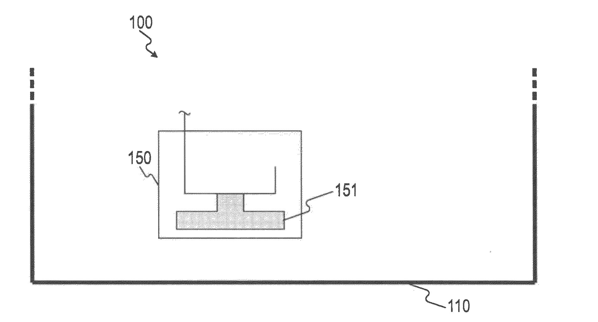
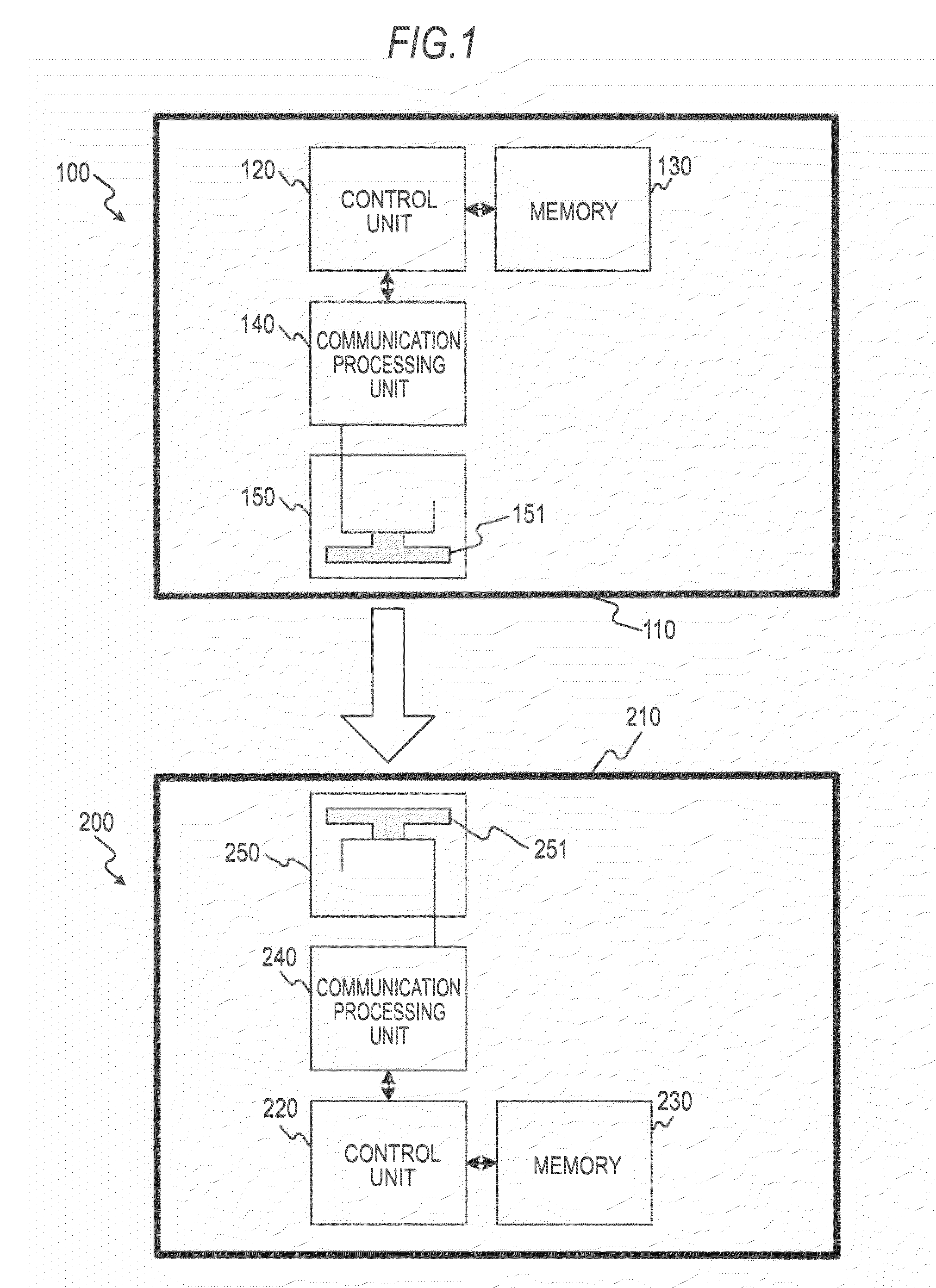
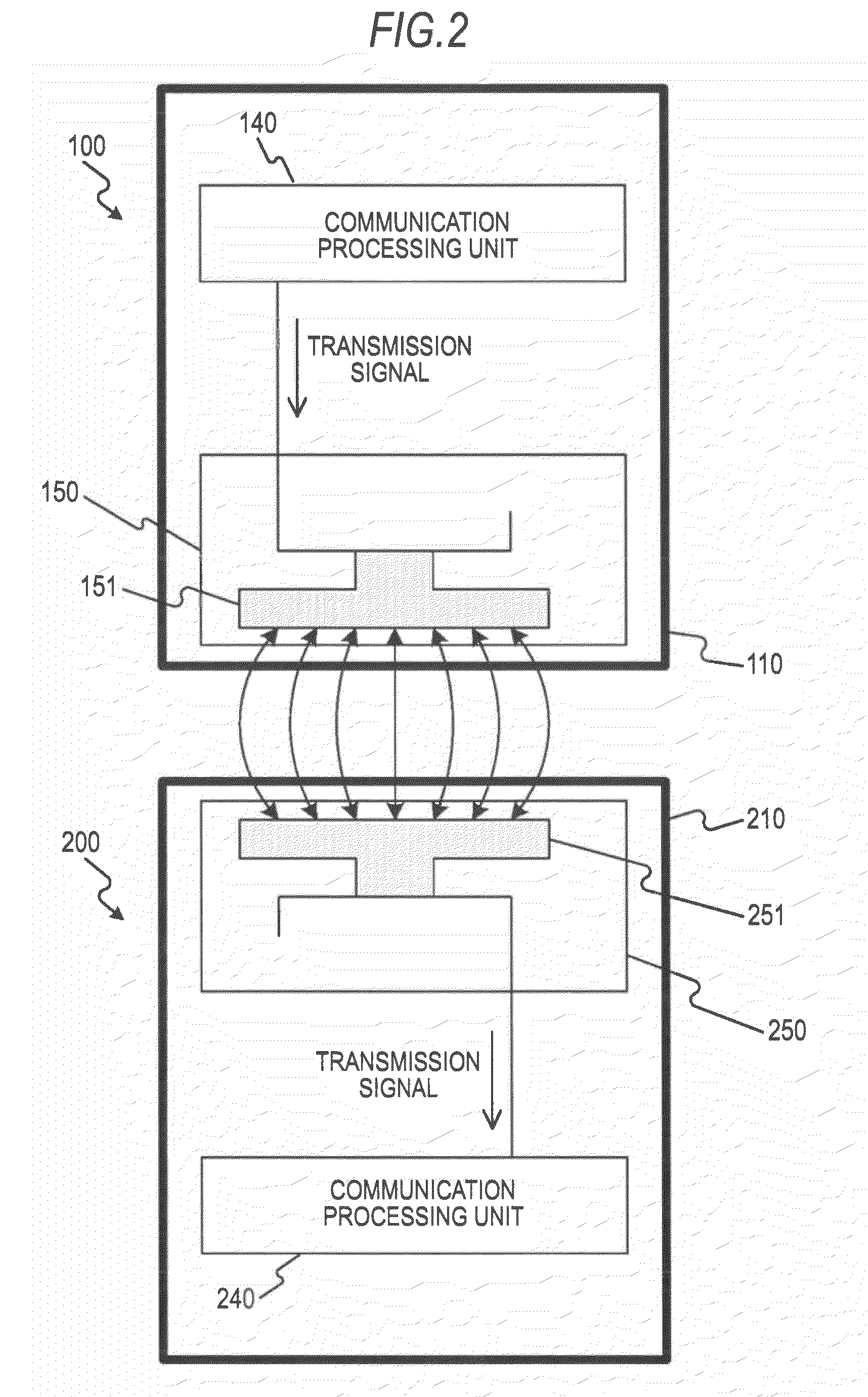
Outline of Near-Field Wireless Communications System

[0039]First, an outline of near-field wireless communications standards with which the embodiments of the invention are compliant will be explained. The near-field wireless communications standards with which the embodiments of the invention are compliant are so-called TransferJet (registered trademark). As its communicable distance, a very short distance of about 3 cm to 5 cm is set, and it is assumed that a considerably high data transfer speed of 560 Mbps at the maximum (effective speed: 375 Mbps) may be obtained within the range of the communicable distance. Further, its network topology (communication mode) is constantly one to one (Point-to-Point).

[0040]In the TransferJet standards, Point-to-Point communications at a communication distance limited to several centimeters is employed as described above, and, for example, the security level comparable to that of wired connection may be obtained without encrypt...

first modified example

[0088]FIGS. 11A and 11B show a configuration example of the electric field reinforcing member 160 as a first modified example in the embodiment of the invention. In the drawings, the same signs are assigned to the same parts as those in FIGS. 4A and 4B and their explanation will be omitted. In an electric field reinforcing member 160A in this case, the slit 165 formed in the electric field reinforcing member 160 as shown in FIGS. 4A and 4B, for example is omitted and the member is formed as a C-shaped flat plate as known from the front view of FIG. 11A. That is, the electric field reinforcing member 160A in this case is formed not in the looped shape but as a flat plate having a C-shaped outer shape.

[0089]Note that, the size of the electric field reinforcing member 160A may be specified in the same manner as that of the electric field reinforcing member 160 of the first embodiment of the invention. That is, as shown in FIG. 12, the size should be set so that the above described equa...

second modified example

[0093]FIGS. 14A to 14C show a configuration example of an electric field reinforcing member 160B as a second modified example in the embodiment of the invention. In the electric field reinforcing members 160 and 160A that have been shown in FIGS. 4A and 4B and 11A and 11B, the C-shapes are formed as the flat surface shapes of the plates. On the other hand, in the electric field reinforcing member 160B of the second modified example, a C-shape is formed by bending a rectangular plate as known from the perspective view of FIG. 14A. That is, the entire shape formed by its thickness part is C-shaped.

[0094]Also, in this case, setting the size so that the lengths L1, L2, L3 of the inner three sides forming the C-shape may satisfy the equation (1) is the same as in the cases of the first embodiment and the first modified example of the invention. Further, setting the lengths L1, L2, L3 in response to the wavelength shortened according to the shortening rate in the case where the electric f...


PUM


Abstract

An electronic apparatus includes: an electric field reinforcing member as a plate-like metal provided in a predetermined position within an outer casing set in response to a specified position of a coupler for generating electric field coupling between a communication destination coupler located within a predetermined communicable distance and itself within the outer casing, having an outer shape in which two leg parts having a positional relationship spaced from each other and a joining part joining the respective one ends of the leg parts are integrally formed, and having lengths of side parts forming an interior of the outer shape set based on a half of a wavelength in response to an electric field frequency generated by the electric field coupling.

Description

BACKGROUND OF THE INVENTION[0001]1. Field of the Invention[0002]The present invention relates to an electronic apparatus and a communication device, and specifically, to an electronic apparatus and a communication device used for near-field wireless communications by electric field coupling.[0003]2. Description of the Related Art[0004]For example, near-field wireless communications standards called TransferJet (registered trademark) is being put into practical use (for example, see TransferJet Whitepaper, TransferJet Consortium (http / / www.transferjet.org / tj / transferjet_whitepaper_J.pdf)). In the near-field wireless communications standards, a very short communicable distance of about 3 to 5 cm is specified.[0005]Further, in TransferJet, an induction phenomenon by electric field coupling is utilized for realization of the communications limited within a near-field range, and an electric field coupler called “coupler” corresponding to an antenna is used. That is, a coupler that one co...

Claims


Application Information

Patent Timeline
IPC IPC(8): H01F27/02
CPCH04B5/0012H01Q1/2208H04B5/22
Inventor UNNO, KEISUKE
Owner SONY CORP
Why Eureka
Try Eureka